► PROJECT | Reference designs ![]()
This functionality can be used for simultaneous display of various designs to compare each other and for purposeful modification.
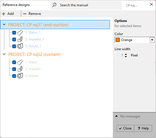
Using the Add-button any reference project (*.CFT- file) can be added. All components of the reference project are grouped under the selected file name.
Each component has its own color and line width (panel Options). Multiple components can be selected using <Shift> and <Ctrl> keys. Clicking on the group header area selects all components of the corresponding project, <Ctrl> <A> selects all components.
With the Remove-button the selected reference project with all its components can be deleted from the list. However single reference components may be deactivated by the check box at the beginning of the line.
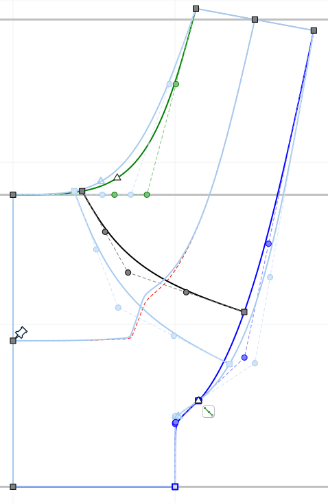
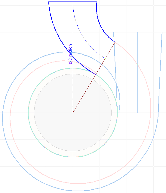
Display in dialogs
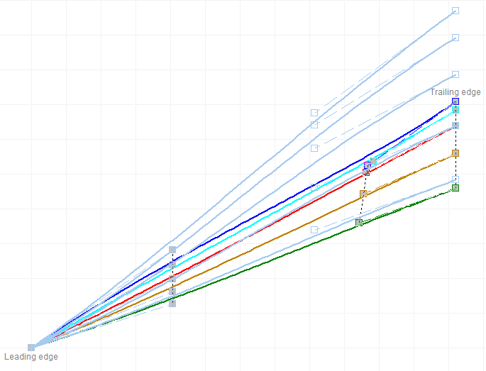
Reference geometries are displayed in the dialogs with selected color and line width.
|
|
|
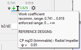
Numerical values appear as hints on input fields when the mouse is moved over it. |
|
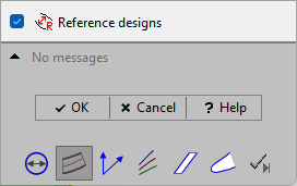
Down right in the design step dialog windows you can completely switch off the display of reference geometries. |
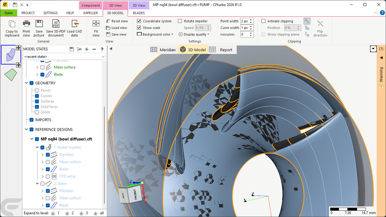
Display in 3D-model
Reference geometry is displayed as 3D model additionally.
All reference geometries are arranged in the model tree in the region "REFERENCE DESIGNS", whereas the single parts can be configured like the normal geometry.