Contours
The most common contours for the propeller acoustic simulation are the acoustic power and the acoustic power level across the domain.
Broadband Source (steady) model
The steps to create contours in the broadband model are:
- Click Load Results in the Simulation Panel.
- Select the required result file in the ensuing Load Results dialog box, click Open.
Create a section
A section is created with the following steps.
- Click Create a Cross-Section
 in the Geometric Entities Panel. A new section Section 01 is created under Derived Surfaces.
 - Select Section 01 under Derived Surfaces.
- Select Plane X for Type and enter Position as 0 m in the Geometry Tab of Properties Panel.
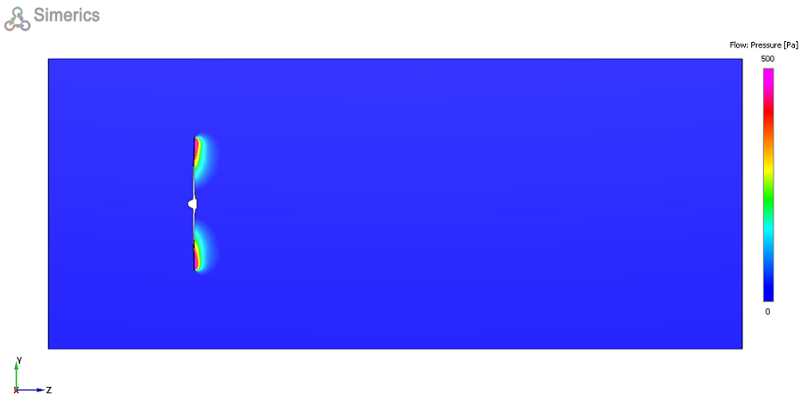
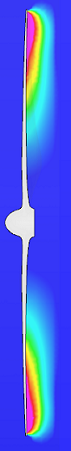
Pressure Contours
- Select Section 01 under Derived Variables in the Geometric Entities Panel.
- Select Pressure from the Flow Variables list under Variable drop-down list in the Results Panel (see, ). For variables and legends, refer Post-Processing.
- Specify Min as 0 and Max as 500 in the Results Panel.
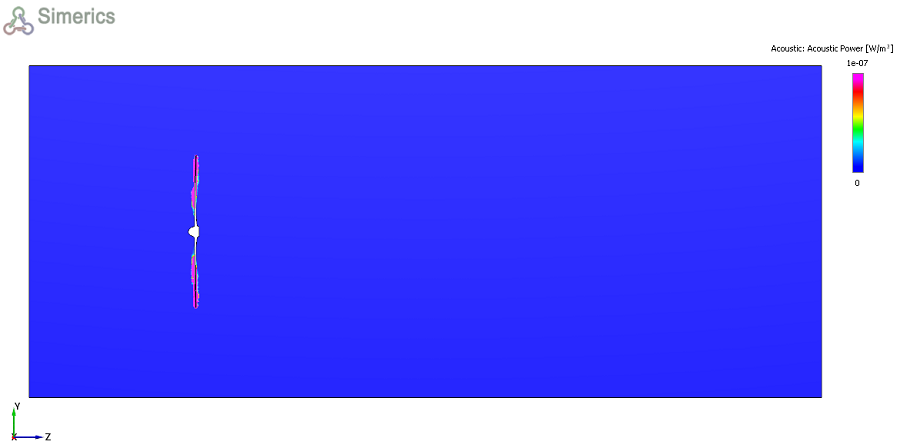
Acoustic power Contours
- Select Section 01 under Derived Variables in the Geometric Entities Panel.
- Select Acoustic power from the Derived Variables list under Variable drop-down list in the Results Panel see, . For variables and legends, refer Post-Processing.
- Specify Min as 0 and Max as 1e-07 in the Results Panel.

|
Note: The same steps can be used to obtain contours for all the variables under the Variable option in the Results Panel. Changes to the display, such as legend, contour color, image sizing, transparency can be made under the View Tab of Properties Panel. |