Building the Mesh
This section describes the step-by-step procedure to prepare the mesh for the propeller acoustics simulation.
The mesh for the computational domain is created using the General Mesher. The settings for the mesh generation are explained in Figure 11.362 and Figure 11.363.
Propeller mesh
- Select General Mesher in the Mesh Panel.
- Select Extended Mode for Setup Options.
-
Select propeller_side1, propeller_side2, propeller_top and propeller_ propeller from the CAD Surfaces in the Geometric Entities Panel and click Add Surfaces icon for CAD Surfaces in the Properties Panel. icon for CAD Surfaces in the Properties Panel.
- Enter the Maximum Cell Size as 0.0125, Minimum Cell Size as 0.0001 and Cell Size on Surfaces as 0.00625 in the Properties Panel.
- Ensure Biggest volume is selected for the Volume options.
- Click Create Mesh. A new mesh is created under Built Meshes in the Geometric Entities Panel.
- The meshed Volume propeller is generated under Volumes.
|
|
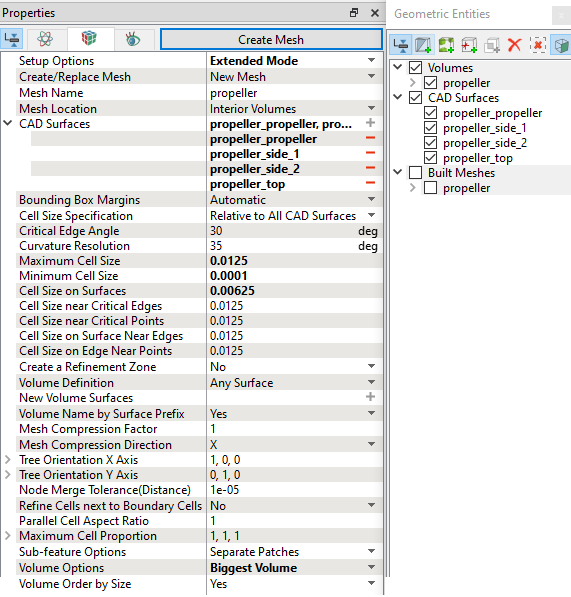
Figure 11.362 - Propeller mesh settings
|
Enclosure mesh
- Select General Mesher in the Mesh Panel.
-
Select Extended Mode for Setup Options.
- Enter Mesh Name as enclosure.
- Select Exterior Volumes for Mesh Location.
-
Select propeller_side1, propeller_side2 and propeller_top from the CAD Surfaces in the Geometric Entities Panel and click Add Surfaces icon for CAD Surfaces in the Properties Panel.
- Select Nonuniform for the Bounding Box Margins.
- Enter Minimum Side Sizes as 0.5, 0.5, 6 and Maximum Side Sizes as 0.5, 0.5, 24.
- Enter Maximum Cell Size as 0.05 Minimum Cell Size as 0.0001 and Cell Size on Surfaces as 0.025.
- Select Cylindrical Zone under Create a Refinement Zone drop-down list.
- Enter the parameter under the Refine Zone Options list as follows:
- Cell Size: 0.0125
Top Circle Center: 0, 0, -0.03 m Bottom Circle Center: 0, 0, 0.03 m Zone Radius: 0.14
- Click Create Mesh. A new mesh is created under Built Meshes in the Geometric Entities Panel.
- The meshed Volume enclosure is generated under Volumes.
|
|
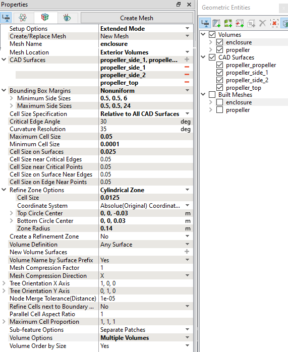
Figure 11.363 - Enclosure mesh settings
|
| ´ |
Note: The mesh can be edited/replaced by selecting it under Built Meshes, and modify the mesh parameters in the Properties Panel. Click Create Mesh to reflect the changes. |
The mesh created for the fluid domain is shown below:
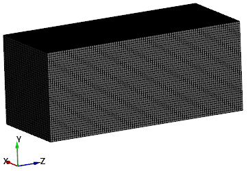
Figure 11.364 - Enclosure mesh
|
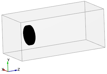
Figure 11.365 - Propeller zone mesh
|
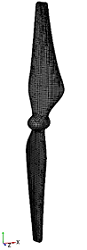
Figure 11.366 - Propeller surface mesh
|
Create interfaces
In this section, the Mismatched Grid Interfaces (MGIs) are generated between boundaries.
The steps to create the MGIs are shown below:
- In Geometric Entities Panel > Volumes > Boundaries, select Boundaries as shown in Table 11.14.
- Click Connect Selected Boundaries via MGI
 icon to create the MGI entities (see Figure 11.367).
A group display of entities can be viewed using the Group Entities by Volumes/Types  icon at Geometric Entities Panel toolbar.
| Enclosure and Propeller |
propeller_side_1 and propeller_side_1_1 |
MGI01 |
| propeller_side_2 and propeller_side_2_1 |
MGI02 |
| propeller_top and propeller_top_1 |
MGI03 |
Table 11.14 - Creating interfaces
| ´ |
Note: If MGIs are created by connecting the wrong Boundaries, delete the created MGIs by clicking on Delete Selected Geometric Entity icon and then recreate the MGIs. icon and then recreate the MGIs.
|
The new entities are created under MGI in Volumes (see Figure 11.368).
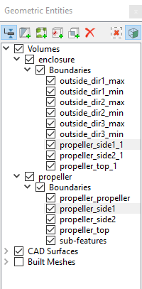
Figure 11.367 - Connecting Boundaries
|
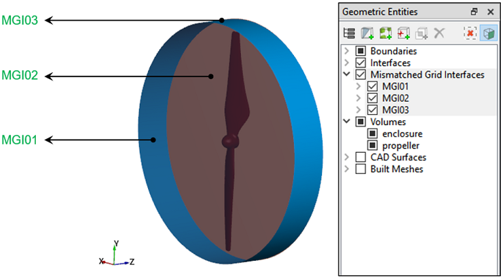
Figure 11.368 - Created interfaces
|