|
You are here: Automotive Templates and Tutorials > Automotive Tutorials > Journal Bearing Tutorial > Contours
|
Contours
The most common contours for the bearing simulation are the pressure, and the total gas volume fraction across the domain. The steps to create contours are:
- Click Load Results in the Simulation Panel.
- Select the required result file "(bearing_model_1440.sres)" in the ensuing Load Results dialog box, click Open.
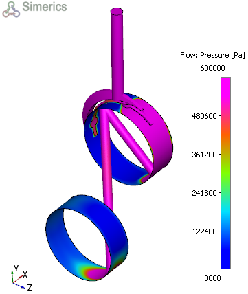
Pressure Contours
- Select Volumes in the Geometric Entities Panel.
- Select Pressure from the Variables list under Variable drop-down list in the Results Panel (see, Figure 7.166). For variables and legends refer, Post-Processing.
- Specify Min as 30000 Pa and Max as 600000 Pa in the Results Panel.
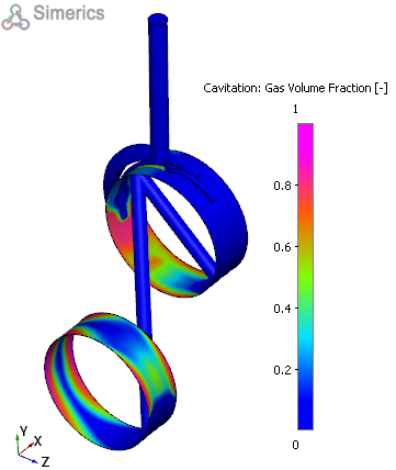
Total Gas Volume Fraction contours
This gives information about the cavitation and aeration occurring in the bearing.
- Select Volumes, in the Geometric Entities Panel.
- Select Total Gas Volume Fraction from the Derived Variables list under Variable drop-down list in the Results Panel (see, Figure 7.167).
- Specify Min as 0 and Max as 1 in the Results Panel.
| ´ | Note: Changes to the display, such as legend, contour color, image sizing, transparency can be made under the View Tab of Properties Panel. |