Computational domain
This section explains the preparation of surfaces to create the domain. This is done with the operations splitting, combining and renaming of the surfaces.
Bearing Surfaces
- Select CAD Surfaces singlebearing in the Geometric Entities Panel.
- Select Split/Combine Geometry or Grid in the Mesh Panel.
- Select Split Disconnected from the Operation drop-down list in the Properties Panel, click Split Disconnected. Three new CAD Surfaces are created in the Geometric Entities Panel.
-
Rename the three new CAD Surfaces singlebearing_01, singlebearing_02, singlebearing_03 as crossdrill, oilgallery and groove respectively in the Geometric Entities Panel.
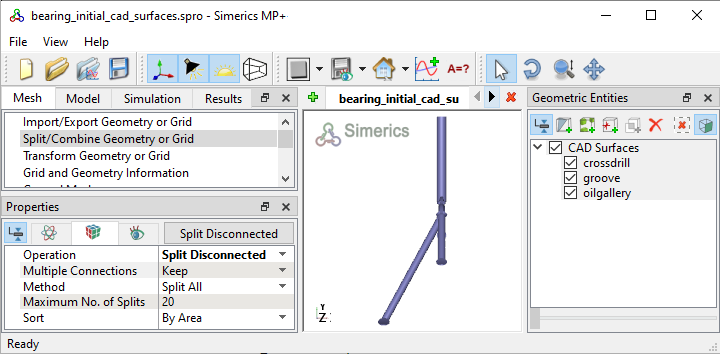
Figure 7.137 - Split of CAD surfaces
Cross drill Surfaces
- Select CAD Surfaces crossdrill in the Geometric Entities Panel.
- Select Split by Angle from the Operation drop-down list in the Properties Panel.
- Enter 75 deg for Angle, click Split by Angle. Four new CAD Surfaces are created.
- Rename the CAD Surfaces crossdrill_01 and crossdrill_02 as crossdrill_wall and crossdrill_mgi_conrod respectively in the Geometric Entities Panel.
- Select the remaining CAD Surfaces and select Combine from the Operation drop-down list in the Properties Panel, click Combine.
- Rename the combined CAD Surfaces as crossdrill_mgi_mb.
|
|
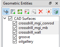
Figure 7.138 - Cross drill surfaces
|
Groove Surfaces
- Select CAD Surfaces groove in the Geometric Entities Panel.
- Select Split by Angle from the Operation drop-down list in the Properties Panel.
- Enter 75 deg for Angle, click Split by Angle. Seven new CAD Surfaces entities are created.
- Rename the CAD Surfaces groove_02 as groove_mgi_mb in the Geometric Entities Panel.
- Select the groove_03 and groove_04 CAD Surfaces and select Combine from the Operation drop-down list in the Properties Panel, click Combine.
- Rename the combined CAD Surfaces as groove_mgi_oilgallery.
- Select the remaining CAD Surfaces and select Combine from the Operation drop-down list in the Properties Panel, click Combine.
- Rename the combined CAD Surfaces as groove_wall.
|
|
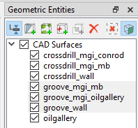
Figure 7.139 - Groove surfaces
|
Oil gallery Surfaces
- Select CAD Surfaces oilgallery in the Geometric Entities Panel.
- Select Split by Angle from the Operation drop-down list in the Properties Panel.
- Enter 75 deg for Angle, click Split by Angle. Four new CAD Surfaces are created in the Geometric Entities Panel.
- Rename the CAD Surfaces oilgallery_02 and oilgallery_03 as oilgallery_mgi_groove and oilgallery_inlet respectively.
- Select the remaining outlet CAD Surfaces and select Combine from the Operation drop-down list in the Properties Panel, click Combine.
- Rename the combined CAD Surfaces as oilgallery_wall.
|
|
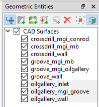
Figure 7.140 - Oil gallery surfaces
|
| ´ |
Note: Splitting of the surfaces can also be done by mouse selection using the Split by Mouse option from the Method drop-down list in the Geometry Tab of Properties Panel. |
Cylindrical Projection-Groove
Cylindrical Projection operation is performed to attain perfect cylindrical shape of the CAD Surfaces. Generally, the CAD Surfaces exported in .STL file contain inaccuracies. Hence, it needs to be corrected.
- Select CAD Surfaces groove_mgi_mb in the Geometric Entities Panel.
- Select Transform Geometry or Grid in the Mesh Panel.
- Select Cylindrical Projection from the Operation drop-down list in the Properties Panel.
- Enter the following:
- Click Cylindrical Projection in the Properties Panel.
|
|
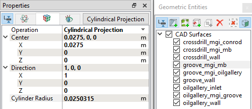
Figure 7.141 - Groove projection
|
Cylindrical Projection-Crossdrill
- Select CAD Surfaces crossdrill_mgi_conrod in the Geometric Entities Panel.
- Select Transform Geometry or Grid in the Mesh Panel.
- Select Cylindrical Projection from the Operation drop-down list in the Properties Panel.
- Enter the following:
- Click Cylindrical Projection in the Properties Panel.
|
|
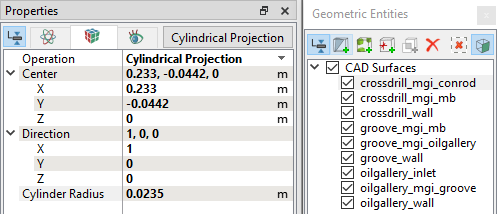
Figure 7.142 - Crossdrill projection
|