Building the Mesh
This section describes the step-by-step procedure for preparing the mesh for the bearing. The Template Mesh/Surface is used to create the mesh for the shaft bearing or main bearing (mb) and connecting rod bearing (conrod). The General Mesher is used to create the mesh for the cross drill, groove and oil gallery.
Connecting rod bearing Mesh
To generate a mesh for connecting rod and shaft bearing, the Annulus option is used.
- Select Template Mesh/Surface in the Mesh Panel.
- Select Annulus from the Shape drop down list in the Geometry Tab of the Properties Panel.
- Enter conrod for Mesh Name.
-
Enter the parameters as follows:
-
Enter the parameters as follows:
- Reference Point: 0.22515, -0.0442, 0
- 1st Point: 0.24115, -0.0442, 0
- Pie Angle: 360
- Inner Radius: 0.0235
- Outer Radius: 0.0235305
- No. of Grid in 1st Dir: 20
- No. of Grid in 2nd Dir: 3
- No. of Grid in 3rd Dir: 540
- Click Build Annus Mesh. A new mesh conrod is created under Built Meshes in the Geometric Entities Panel.
- The meshed volume conrod is generated under Volumes.
- Rename conrodBoundariescylinder, cylinder_min, dir_max and dir_min as conrod_outer, conrod_inner, conrod_outlet_u and conrod_outlet_d respectively in the Geometric Entities Panel.
|
|
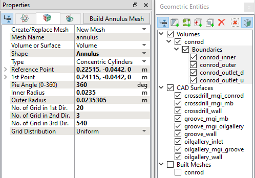
Figure 7.143 - Connecting rod mesh settings
|
Shaft bearing Mesh
- Select Template Mesh/Surface in the Mesh Panel.
- Select Annulus from the Shape drop-down list in the Geometry Tab of Properties Panel.
- Enter mb for Mesh Name.
-
Enter the parameters as follows:
- Reference Point: 0.266, 0, 0
- 1st Point: 0.284, 0, 0
- Pie Angle: 360
- Inner Radius: 0.025
- Outer Radius: 0.0250315
- No. of Grid in 1st Dir: 20
- No. of Grid in 2nd Dir: 3
- No. of Grid in 3rd Dir: 540
- Click Build Annus Mesh. The new mesh mb is created under Built Meshes in the Geometric Entities Panel.
- The meshed volume mb is generated under Volumes.
- Rename mbBoundariescylinder, cylinder_min, dir_max and dir_min as mb_outer, mb_inner, mb_outlet_u and mb_outlet_d respectively in the Geometric Entities Panel.
|
|
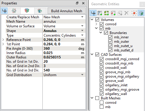
Figure 7.144 - Shaft bearing mesh settings
|
Crossdrill Mesh
- Select General Mesher in the Mesh Panel.
- Select CAD Surfaces crossdrill_mgi_conrod, crossdrill_mgi_mb and crossdrill_wall in the Geometric Entities Panel and click Add Surfaces
 icon for CAD Surfaces in the Properties Panel. icon for CAD Surfaces in the Properties Panel.
- Enter Maximum Cell Size as 0.005, Minimum Cell Size as 5e-05 and Cell Size on Surfaces as 0.0025.
- Click Create Mesh. A new mesh crossdrill is created under Built Meshes in the Geometric Entities Panel.
- The meshed volumes crossdrill is generated under Volumes.
|
|
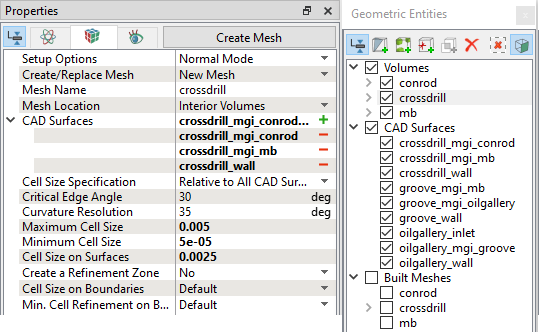
Figure 7.145 - Cross drill mesh settings
|
Groove Mesh
- Select General Mesher in the Mesh Panel.
- Select CAD Surfaces groove_mgi_mb, groove_mgi_oilgallery and groove_wall in the Geometric Entities Panel and click Add Surfaces icon for CAD Surfaces in the Properties Panel.
- Enter Maximum Cell Size as 0.005, Minimum Cell Size as 0.0001 and Cell Size on Surfaces as 0.0025.
- Click Create Mesh. A new mesh groove is created under Built Meshes in the Geometric Entities Panel.
- The meshed volumes groove is generated under Volumes.
|
|
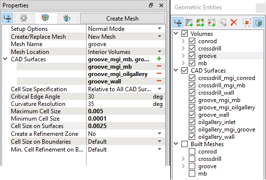
Figure 7.146 - Groove mesh settings
|
Oil Gallery Mesh
- Select General Mesher in the Mesh Panel.
- Select CAD Surfaces oilgallery_inlet, oilgallery_mgi_groove and oilgallery_wall in the Geometric Entities Panel and click Add Surfaces icon for CAD Surfaces in the Properties Panel.
- Enter Maximum Cell Size as 0.005, Minimum Cell Size as 0.0001 and Cell Size on Surfaces as 0.0025.
- Click Create Mesh. A new mesh oilgallery is created under Built Meshes in the Geometric Entities Panel.
- The meshed volumes oilgallery is generated under Volumes.
|
|
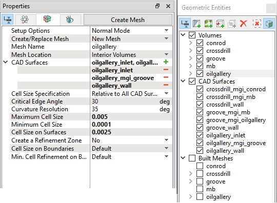
Figure 7.147 - Oil gallery mesh settings
|
| ´ |
Note: The mesh can be edited/replaced by selecting it under Built Meshes and modify the mesh parameters in the Properties Panel. Click Create Mesh to reflect the changes. |
The mesh created for the fluid domain is shown below:
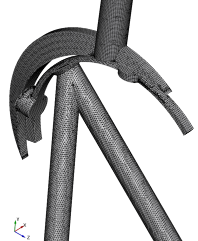 Figure 7.148 - Cross drill, groove and oil gallery mesh | | 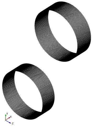 Figure 7.149 - Conrod and mb mesh |
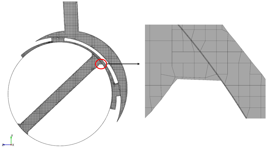
Figure 7.150 - Sectional view
Create interfaces
In this section, the MGIs are generated between boundaries.
The steps to create the MGIs are shown below:
- Geometric Entities Panel > Volumes > Boundaries, select Boundaries as shown in Table 7.3.
- Click Connect Selected Boundaries via MGI
 icon to create the MGI entities (see, Figure 7.151).
A group display of entities can be viewed using the Group Entities by Volumes/Types  icon in Geometric Entities Panel toolbar.
| Conrod and cross drill
|
conrod_inner and crossdrill_mgi_conrod |
MGI01
|
| Cross drill and mb
|
crossdrill_mgi_mb and mb_inner |
MGI02
|
| Groove and mb
|
groove_mgi_mb and mb_outer |
MGI03
|
| Oil gallery and groove |
oilgallery_mgi_groove and groove_mgi_oilgallery
|
MGI04
|
Table 7.3 - Creating interfaces
The new entities are created under MGI in Volumes (see, Figure 7.152).
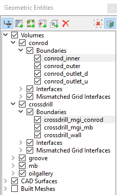
Figure 7.151 - Connecting conrod and cross drill
|
|
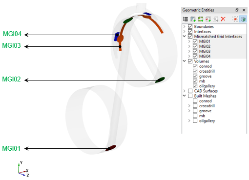
Figure 7.152 - Created interfaces
|
| |
Note: If MGIs are created by connecting the wrong boundaries, delete the created MGIs by clicking on Delete Selected Geometric Entity  icon and then recreate the MGIs. icon and then recreate the MGIs.
|