|
You are here: Automotive Templates and Tutorials > Automotive Tutorials > Journal Bearing Tutorial > Defining Physics and Conditions
|
Defining Physics and Conditions
The physics and conditions are specified as follows:
Adding Modules
|
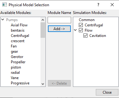
Figure 7.153 - Adding modules |
General Operating Parameters
|
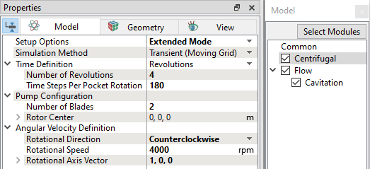
Figure 7.154 - Operating parameters |
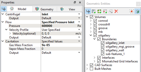
Flow Parameters
- Select Flow in the Model Panel.
- Enter 0.3 for Velocity and Pressure under Relaxation in the Model Panel of Properties Panel.
- Select Cavitation in the Model Panel.
- Select Variable Gas Mass Fraction under Model drop-down in the Model Panel of Properties Panel.
- Enter 0.5 for Vapor Mass Fraction and Gas Mass Fraction under Relaxation.
- Enter 0 for Vapor Mass Fraction and Gas Mass Fraction under Diagonal Relaxation.
Boundary Conditions
Rotor
- Click crossdrill_wall Boundaries list in the Geometric Entities Panel.
- Select Rotor under Centrifugal drop-down list in the Model Tab of Properties Panel.
- The values for the Rotor are the same as specified under Centrifugal in the Model Panel.
Rotating Wall
- Click conrod_inner and mb_inner from Boundaries list in the Geometric Entities Panel.
- Select Rotating wall under Centrifugal drop-down list in the Model Tab of Properties Panel.
- The values for the Rotating wall are the same as specified under Centrifugal in the Model Panel.
Outlet
|
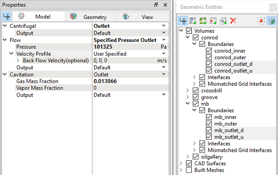
Figure 7.156 - Outlet conditions |
Fluid Properties
|
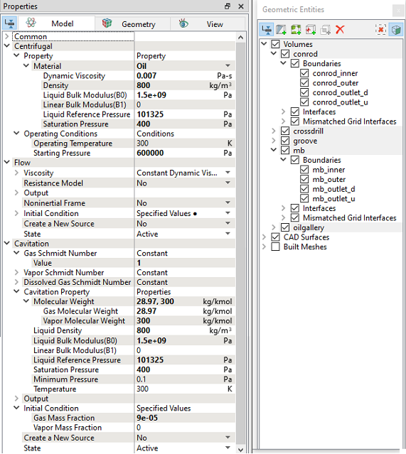
Figure 7.157 - Fluid properties |
Center Orbiting and Deformation
Orbiting: Time dependent movement of inner surface for main bearing and outer surface for conrod bearing due to unbalanced forces during engine operation.
Deformation: Change in the shape of outer surface of a bearing.
Orbiting and Deformation are provided using Volume Remesh option through Global Expressions and Local Expressions inside Simerics-MP+.
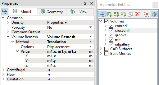
Volume Remeshing
- Global Expressions defines parameters and bearings orbiting movement.
- Local Expressions define bearings deformation.
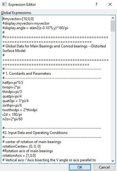
Global Expression
#myvector=[10,0,0] #display.myvector=myvector #display.angle = atan2(z-0.1075,y)*180/pi # #================================================================================ # Global Data for Main Bearings and Conrod bearings --Distorted Surface Model # ================================================================================ #---------------------------------------------------------------- # 1. Constants and Parameters #---------------------------------------------------------------- halfpi=pi*0.5 twopi=2*pi thirdpi=pi/3 quatpi=pi/4 quat3pi = 3*pi/4 sixthpi=pi/6 twothirdpi = 2*thirdpi r2d = 180/pi n2o=2*pi/60 #---------------------------------------------------------------- #2. Input Data and Operating Conditions: #---------------------------------------------------------------- # center of rotation of main bearings rotationCenter= [0, 0, 0] #Rotation axis of main bearings rotationAxis = [1,0,0] # Vertical axis :"Axis bisecting the V angle or axis parallel to cylinder axis" in case of inline cylinders V_Axis = [0,1,0] # Horizontal axis H_Axis = V_Axis^rotationAxis #cylinder offset for inline engines in meter from vertical axis delta = 0 # zero(0) for V-cylinder engines #Cylinder axis angle from Horizontal axis for bank 1 and bank 2 #For V-12 cylinders with V angle 60 degree alpha1 = pi/2 #Bank 1 alpha2 = pi/2 #Bank 2 #Engine rotation in rpm (absolute) rpm = 4000 n = 1 # for clockwise rotation n = 2 and counterclockwise n =1 bank_angle = 0 # angle between two banks (V-angle), positive if orientation(bank1 to bank 2) is along the direction of rotation; negative if opposite to the direction of rotation equals zero(0) for inline cylinder engines no_of_cylinders = 1 #firing interval angle: crank angle rotation between two successive firing; firing_interval_angle = 4*pi/no_of_cylinders #Engine cylinder firing order #12-9-10-5-6-1-2-3-4-7-8-11 ref_cyl_no = 1 # 1st fired cylinder number theta_ref = -pi/2 # initial angular position of the conrod bearing for the 1st fired cylinder from the Horizontal Axis #Firing order positon of cylinders #Default value is ‘ref_cyl_no’ if cylinders are absent cyl_1 = 1 # Here cylinder 1 is the 1st fired cylinder cyl_2 = 3 # Cylinder 2 fires at 3rd position cyl_3 = 5 cyl_4 = 2 cyl_5 = 4 cyl_6 = 6 cyl_7 = ref_cyl_no #Default value ‘ref_cyl_no’, change the position value if you have cyl_7 cyl_8 = ref_cyl_no #Default value ‘ref_cyl_no’, change the position value if you have cyl_8 cyl_9 = ref_cyl_no cyl_10 = ref_cyl_no cyl_11 = ref_cyl_no cyl_12 = ref_cyl_no #main bearing inner/outer radius (m) mbri = 0.025 mbro = 0.0250315 #conrod bearing inner/outer radius (m) conri=0.0235 conro=0.0235305 #crankshaft radius(m) rc=0.0442 #conrod length(m) cl=0.137 #ratio of rc over cl rrc=rc/cl #minimum clearance (micron) epsmin=3e-6 # magnifying factor for viewing purpose, has to be 1 for solving fluid flow magnifier = 1 range = 3 # range to determine where the mesh need to be moved #convert time to total rotating angle t2d = time*rpm*6 #crank angle to read in the eccentricity crAngle = mod(t2d,720) # main bearing orbiting distances (get from table with angle in degree, and (y,z) in mm) m1H = table("Mainbearing_orbit_z.txt", crAngle)/1000 m1V = table("Mainbearing_orbit_y.txt", crAngle)/1000 #m2H = table("main_2_y.txt", crAngle)/1000 #m2V = table("main_2_z.txt", crAngle)/1000 #m3H = table("main_1_y.txt", crAngle)/1000 #m3V = table("main_1_z.txt", crAngle)/1000 #m4H = table("main_2_y.txt", crAngle)/1000 #m4V = table("main_2_z.txt", crAngle)/1000 #m5H = table("main_1_y.txt", crAngle)/1000 #m5V = table("main_1_z.txt", crAngle)/1000 #m6H = table("main_2_y.txt", crAngle)/1000 #m6V = table("main_2_z.txt", crAngle)/1000 #m7H = table("main_1_y.txt", crAngle)/1000 #m7V = table("main_1_z.txt", crAngle)/1000 #************************DO NOT CHANGE THESE CALCULATIONS BELOW************************ omega =-1*((-1)^n)*rpm*n2o omegav = omega*rotationAxis omt=time*omega # Initial angular position of the conrod bearings theta1_0 = theta_ref + ((-1)^n)* ((cyl_1- ref_cyl_no)* firing_interval_angle) #theta2_0 = theta_ref + ((-1)^n)* ((cyl_2- ref_cyl_no)* firing_interval_angle - bank_angle) #theta3_0 = theta_ref + ((-1)^n)* ((cyl_3- ref_cyl_no)* firing_interval_angle) #theta4_0 = theta_ref + ((-1)^n)* ((cyl_4- ref_cyl_no)* firing_interval_angle - bank_angle) #theta5_0 = theta_ref + ((-1)^n)* ((cyl_5- ref_cyl_no)* firing_interval_angle) #theta6_0 = theta_ref + ((-1)^n)* ((cyl_6- ref_cyl_no)* firing_interval_angle - bank_angle) #theta7_0 = theta_ref + ((-1)^n)* ((cyl_7- ref_cyl_no)* firing_interval_angle) #theta8_0 = theta_ref + ((-1)^n)* ((cyl_8- ref_cyl_no)* firing_interval_angle - bank_angle) #theta9_0 = theta_ref + ((-1)^n)* ((cyl_9- ref_cyl_no)* firing_interval_angle) #theta10_0 = theta_ref + ((-1)^n)* ((cyl_10- ref_cyl_no)* firing_interval_angle - bank_angle) #theta11_0 = theta_ref + ((-1)^n)* ((cyl_11- ref_cyl_no)* firing_interval_angle) #theta12_0 = theta_ref + ((-1)^n)* ((cyl_12- ref_cyl_no)* firing_interval_angle - bank_angle) # the theta's dictate the instantaneous angular position of the conrod bearing w.r.t. Horizontal axis theta1 = theta1_0 + omt #theta2 = theta2_0 + omt #theta3 = theta3_0 + omt #theta4 = theta4_0 + omt #theta5 = theta5_0 + omt #theta6 = theta6_0 + omt #theta7 = theta7_0 + omt #theta8 = theta8_0 + omt #theta9 = theta9_0 + omt #theta10 = theta10_0 + omt #theta11 = theta11_0 + omt #theta12 = theta12_0 + omt #************************DO NOT CHANGE THESE CALCULATIONS ABOVE************************ # conrod bearing orbiting distances (get from table with angle in degree, and (y,z) in mm) rod1H = table("Conrodbearing_orbit_z.txt", mod((theta1*r2d),720))/1000 rod1V = table("Conrodbearing_orbit_y.txt", mod((theta1*r2d),720))/1000 #rod2H = table("conrod_y.txt", mod((theta2*r2d),720))/1000 #rod2V = table("conrod_z.txt", mod((theta2*r2d),720))/1000 #rod3H = table("conrod_y.txt", mod((theta3*r2d),720))/1000 #rod3V = table("conrod_z.txt", mod((theta3*r2d),720))/1000 #rod4H = table("conrod_y.txt", mod((theta4*r2d),720))/1000 #rod4V = table("conrod_z.txt", mod((theta4*r2d),720))/1000 #rod5H = table("conrod_y.txt", mod((theta5*r2d),720))/1000 #rod5V = table("conrod_z.txt", mod((theta5*r2d),720))/1000 #rod6H = table("conrod_y.txt", mod((theta6*r2d),720))/1000 #rod6V = table("conrod_z.txt", mod((theta6*r2d),720))/1000 #rod7H = table("conrod_y.txt", mod((theta7*r2d),720))/1000 #rod7V = table("conrod_z.txt", mod((theta7*r2d),720))/1000 #rod8H = table("conrod_y.txt", mod((theta8*r2d),720))/1000 #rod8V = table("conrod_z.txt", mod((theta8*r2d),720))/1000 #rod9H = table("conrod_y.txt", mod((theta9*r2d),720))/1000 #rod9V = table("conrod_z.txt", mod((theta9*r2d),720))/1000 #rod10H = table("conrod_y.txt", mod((theta10*r2d),720))/1000 #rod10V = table("conrod_z.txt", mod((theta10*r2d),720))/1000 #rod11H = table("conrod_y.txt", mod((theta11*r2d),720))/1000 #rod11V = table("conrod_z.txt", mod((theta11*r2d),720))/1000 #rod12H = table("conrod_y.txt", mod((theta12*r2d),720))/1000 #rod12V = table("conrod_z.txt", mod((theta12*r2d),720))/1000 #====================================================================== #************** DO NOT CHANGE ANYTHING BELOW THIS LINE **************** #====================================================================== #3. Calculations #---------------------------------------------------------------- cl2=cl*cl #the gamma’s dictate the instantaneous angular position of the conrod bearing w.r.t. Cylinder axis gamma1 = theta1 - alpha1 #gamma2 = theta2 - alpha2 #gamma3 = theta3 - alpha1 #gamma4 = theta4 - alpha2 #gamma5 = theta5 - alpha1 #gamma6 = theta6 - alpha2 #gamma7 = theta7 - alpha1 #gamma8 = theta8 - alpha2 #gamma9 = theta9 - alpha1 #gamma10 = theta10 - alpha2 #gamma11 = theta11 - alpha1 #gamma12 = theta12 - alpha2 gammai1 = theta_ref - alpha1 #gammai2 = theta20 - alpha2 #gammai3 = theta30 - alpha1 #gammai4 = theta40 - alpha2 #gammai5 = theta50 - alpha1 #gammai6 = theta60 - alpha2 #gammai7 = theta70 - alpha1 #gammai8 = theta80 - alpha2 #gammai9 = theta90 - alpha1 #gammai10 = theta100 - alpha2 #gammai11 = theta110 - alpha1 #gammai12 = theta120 - alpha2 # Distance along the cylinder axis rr1=rc*cos(gamma1) #rr2=rc*cos(gamma2) #rr3=rc*cos(gamma3) #rr4=rc*cos(gamma4) #rr5=rc*cos(gamma5) #rr6=rc*cos(gamma6) #rr7=rc*cos(gamma7) #rr8=rc*cos(gamma8) #rr9=rc*cos(gamma9) #rr10=rc*cos(gamma10) #rr11=rc*cos(gamma11) #rr12=rc*cos(gamma12) rp1 = rr1+(cl2-(rc*sin(gamma1)-delta)^2)^0.5 #rp2 = rr2+(cl2-(rc*sin(gamma2)-delta)^2)^0.5 #rp3 = rr3+(cl2-(rc*sin(gamma3)-delta)^2)^0.5 #rp4 = rr4+(cl2-(rc*sin(gamma4)-delta)^2)^0.5 #rp5 = rr5+(cl2-(rc*sin(gamma5)-delta)^2)^0.5 #rp6 = rr6+(cl2-(rc*sin(gamma6)-delta)^2)^0.5 #rp7 = rr7+(cl2-(rc*sin(gamma7)-delta)^2)^0.5 #rp8 = rr8+(cl2-(rc*sin(gamma8)-delta)^2)^0.5 #rp9 = rr9+(cl2-(rc*sin(gamma9)-delta)^2)^0.5 #rp10 = rr10+(cl2-(rc*sin(gamma10)-delta)^2)^0.5 #rp11 = rr11+(cl2-(rc*sin(gamma11)-delta)^2)^0.5 #rp12 = rr12+(cl2-(rc*sin(gamma12)-delta)^2)^0.5 #Ratio of Crank radius projection to Connecting rod projection pr_ratio1 = rr1/(rr1-rp1) #pr_ratio2 = rr2/(rr2-rp2) #pr_ratio3 = rr3/(rr3-rp3) #pr_ratio4 = rr4/(rr4-rp4) #pr_ratio5 = rr5/(rr5-rp5) #pr_ratio6 = rr6/(rr6-rp6) #pr_ratio7 = rr7/(rr7-rp7) #pr_ratio8 = rr8/(rr8-rp8) #pr_ratio9 = rr9/(rr9-rp9) #pr_ratio10 = rr10/(rr10-rp10) #pr_ratio11 = rr11/(rr11-rp11) #pr_ratio12 = rr12/(rr12-rp12) #connecting rod angle with the cylinder axis alphaP1 = -atan((rc*sin(gamma1)-delta)/(rp1-rr1)) #alphaP2 = -atan((rc*sin(gamma2)-delta)/(rp2-rr2)) #alphaP3 = -atan((rc*sin(gamma3)-delta)/(rp3-rr3)) #alphaP4 = -atan((rc*sin(gamma4)-delta)/(rp4-rr4)) #alphaP5 = -atan((rc*sin(gamma5)-delta)/(rp5-rr5)) #alphaP6 = -atan((rc*sin(gamma6)-delta)/(rp6-rr6)) #alphaP7 = -atan((rc*sin(gamma7)-delta)/(rp7-rr7)) #alphaP8 = -atan((rc*sin(gamma8)-delta)/(rp8-rr8)) #alphaP9 = -atan((rc*sin(gamma9)-delta)/(rp9-rr9)) #alphaP10 = -atan((rc*sin(gamma10)-delta)/(rp10-rr10)) #alphaP11 = -atan((rc*sin(gamma11)-delta)/(rp11-rr11)) #alphaP12 = -atan((rc*sin(gamma12)-delta)/(rp12-rr12)) #conrod-piston angle delta1 =-asin(rrc*sin(gamma1)) #delta2 =-asin(rrc*sin(gamma2)) #delta3 =-asin(rrc*sin(gamma3)) #delta4 =-asin(rrc*sin(gamma4)) #delta5 =-asin(rrc*sin(gamma5)) #delta6 =-asin(rrc*sin(gamma6)) #delta7 =-asin(rrc*sin(gamma7)) #delta8 =-asin(rrc*sin(gamma8)) #delta9 =-asin(rrc*sin(gamma9)) #delta10 =-asin(rrc*sin(gamma10)) #delta11 =-asin(rrc*sin(gamma11)) #delta12 =-asin(rrc*sin(gamma12)) deltai1 =-asin(rrc*sin(gammai1)) #deltai2 =-asin(rrc*sin(gammai2)) #deltai3 =-asin(rrc*sin(gammai3)) #deltai4 =-asin(rrc*sin(gammai4)) #deltai5 =-asin(rrc*sin(gammai5)) #deltai6 =-asin(rrc*sin(gammai6)) #deltai7 =-asin(rrc*sin(gammai7)) #deltai8 =-asin(rrc*sin(gammai8)) #deltai9 =-asin(rrc*sin(gammai9)) #deltai10 =-asin(rrc*sin(gammai10)) #deltai11 =-asin(rrc*sin(gammai11)) #deltai12 =-asin(rrc*sin(gammai12)) beta1 =delta1-deltai1 #beta2 =delta2-deltai2 #beta3 =delta3-deltai3 #beta4 =delta4-deltai4 #beta5 =delta5-deltai5 #beta6 =delta6-deltai6 #beta7 =delta7-deltai7 #beta8 =delta8-deltai8 #beta9 =delta9-deltai9 #beta10 =delta10-deltai10 #beta11 =delta11-deltai11 #beta12 =delta12-deltai12 # Conrod center position cc1 = rc*cos(theta1)*H_Axis + rc*sin(theta1)*V_Axis #cc2 = rc*cos(theta2)*H_Axis + rc*sin(theta2)*V_Axis #cc3 = rc*cos(theta3)*H_Axis + rc*sin(theta3)*V_Axis #cc4 = rc*cos(theta4)*H_Axis + rc*sin(theta4)*V_Axis #cc5 = rc*cos(theta5)*H_Axis + rc*sin(theta5)*V_Axis #cc6 = rc*cos(theta6)*H_Axis + rc*sin(theta6)*V_Axis #cc7 = rc*cos(theta7)*H_Axis + rc*sin(theta7)*V_Axis #cc8 = rc*cos(theta8)*H_Axis + rc*sin(theta8)*V_Axis #cc9 = rc*cos(theta9)*H_Axis + rc*sin(theta9)*V_Axis #cc10 = rc*cos(theta10)*H_Axis + rc*sin(theta10)*V_Axis #cc11 = rc*cos(theta11)*H_Axis + rc*sin(theta11)*V_Axis #cc12 = rc*cos(theta12)*H_Axis + rc*sin(theta12)*V_Axis # Conrod initial center position cci1 = rc*cos(theta_ref)*H_Axis + rc*sin(theta_ref)*V_Axis #cci2 = rc*cos(theta20)*H_Axis + rc*sin(theta20)*V_Axis #cci3 = rc*cos(theta30)*H_Axis + rc*sin(theta30)*V_Axis #cci4 = rc*cos(theta40)*H_Axis + rc*sin(theta40)*V_Axis #cci5 = rc*cos(theta50)*H_Axis + rc*sin(theta50)*V_Axis #cci6 = rc*cos(theta60)*H_Axis + rc*sin(theta60)*V_Axis #cci7 = rc*cos(theta70)*H_Axis + rc*sin(theta70)*V_Axis #cci8 = rc*cos(theta80)*H_Axis + rc*sin(theta80)*V_Axis #cci9 = rc*cos(theta90)*H_Axis + rc*sin(theta90)*V_Axis #cci10 = rc*cos(theta100)*H_Axis + rc*sin(theta100)*V_Axis #cci11 = rc*cos(theta110)*H_Axis + rc*sin(theta110)*V_Axis #cci12 = rc*cos(theta120)*H_Axis + rc*sin(theta120)*V_Axis dummy_axis = [1,1,1] #Main bearing orbiting m1 = (m1H*H_Axis/(H_Axis&dummy_axis)+m1V*V_Axis/(V_Axis&dummy_axis))*magnifier #m2 = (m2H*H_Axis/(H_Axis&dummy_axis)+m2V*V_Axis/(V_Axis&dummy_axis))*magnifier #m3 = (m3H*H_Axis/(H_Axis&dummy_axis)+m3V*V_Axis/(V_Axis&dummy_axis))*magnifier #m4 = (m4H*H_Axis/(H_Axis&dummy_axis)+m4V*V_Axis/(V_Axis&dummy_axis))*magnifier #m5 = (m5H*H_Axis/(H_Axis&dummy_axis)+m5V*V_Axis/(V_Axis&dummy_axis))*magnifier #m6 = (m6H*H_Axis/(H_Axis&dummy_axis)+m6V*V_Axis/(V_Axis&dummy_axis))*magnifier #m7 = (m7H*H_Axis/(H_Axis&dummy_axis)+m7V*V_Axis/(V_Axis&dummy_axis))*magnifier #Conrod bearing orbiting rod1 = (rod1H*H_Axis/(H_Axis&dummy_axis) + rod1V*V_Axis/(V_Axis&dummy_axis))*magnifier #rod2 = (rod2H*H_Axis/(H_Axis&dummy_axis) + rod2V*V_Axis/(V_Axis&dummy_axis))*magnifier #rod3 = (rod3H*H_Axis/(H_Axis&dummy_axis) + rod3V*V_Axis/(V_Axis&dummy_axis))*magnifier #rod4 = (rod4H*H_Axis/(H_Axis&dummy_axis) + rod4V*V_Axis/(V_Axis&dummy_axis))*magnifier #rod5 = (rod5H*H_Axis/(H_Axis&dummy_axis) + rod5V*V_Axis/(V_Axis&dummy_axis))*magnifier #rod6 = (rod6H*H_Axis/(H_Axis&dummy_axis) + rod6V*V_Axis/(V_Axis&dummy_axis))*magnifier #rod7 = (rod7H*H_Axis/(H_Axis&dummy_axis) + rod7V*V_Axis/(V_Axis&dummy_axis))*magnifier #rod8 = (rod8H*H_Axis/(H_Axis&dummy_axis) + rod8V*V_Axis/(V_Axis&dummy_axis))*magnifier #rod9 = (rod9H*H_Axis/(H_Axis&dummy_axis) + rod9V*V_Axis/(V_Axis&dummy_axis))*magnifier #rod10 = (rod10H*H_Axis/(H_Axis&dummy_axis) + rod10V*V_Axis/(V_Axis&dummy_axis))*magnifier #rod11 = (rod11H*H_Axis/(H_Axis&dummy_axis) + rod11V*V_Axis/(V_Axis&dummy_axis))*magnifier #rod12 = (rod12H*H_Axis/(H_Axis&dummy_axis) + rod12V*V_Axis/(V_Axis&dummy_axis))*magnifier
|
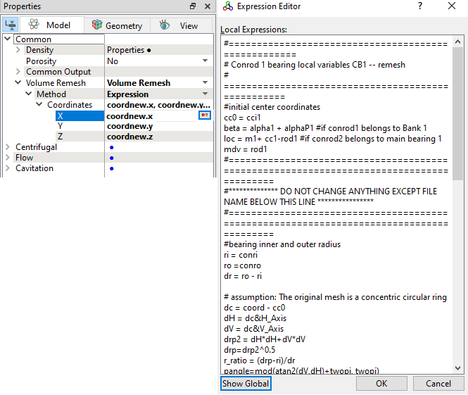
Conrod Local Expression
#==================================================== # Conrod 1 bearing local variables CB1 -- remesh # =================================================== #initial center coordinates cc0 = cci1 beta = alpha1 + alphaP1 #if conrod1 belongs to Bank 1 loc = m1+ cc1-rod1 #if conrod2 belongs to main bearing 1 mdv = rod1 #======================================================================================== #************** DO NOT CHANGE ANYTHING EXCEPT FILE NAME BELOW THIS LINE **************** #======================================================================================== #bearing inner and outer radius ri = conri ro =conro dr = ro - ri # assumption: The original mesh is a concentric circular ring dc = coord - cc0 dH = dc&H_Axis dV = dc&V_Axis drp2 = dH*dH+dV*dV drp=drp2^0.5 r_ratio = (drp-ri)/dr pangle=mod(atan2(dV,dH)+twopi, twopi) #new position angle due to conrod rotation anew = pangle + beta #assume mesh rotate with inner shell aout = pangle*r2d #deg #mapping with the provided table convention aout_mod = (aout>0)? mod(aout, 360) : 360 - mod(-aout, 360) rin = ri # text file unit is mm rout_tmp1 = table("Conrodbearing_distorted.txt", aout_mod)/1000 #File unit is in mm #rout_tmp1 = ro rout = rin + (rout_tmp1-rin)*magnifier cosanew = cos(anew) sinanew = sin(anew) a = cosanew*H_Axis+sinanew*V_Axis # calculate inner radius which changes due to both rod orbiting and MB orbiting md = len(mdv)+1e-30 md2 = md^2 adotmd=a&mdv cosalpha=adotmd/md bb =md*cosalpha cc = rin^2-md2 rin_tmp1 = bb + sqrt(bb^2 + cc) rin_tmp = rin_tmp1<(rout - epsmin)?rin_tmp1:(rout-epsmin) rnew = rin_tmp + (rout-rin_tmp)*r_ratio # rotation + main bearing orbiting + outer shell reverse conrod orbiting coordnew = rnew*a+ loc + (coord&rotationAxis)*rotationAxis
|
Crossdrill Local Expression
|
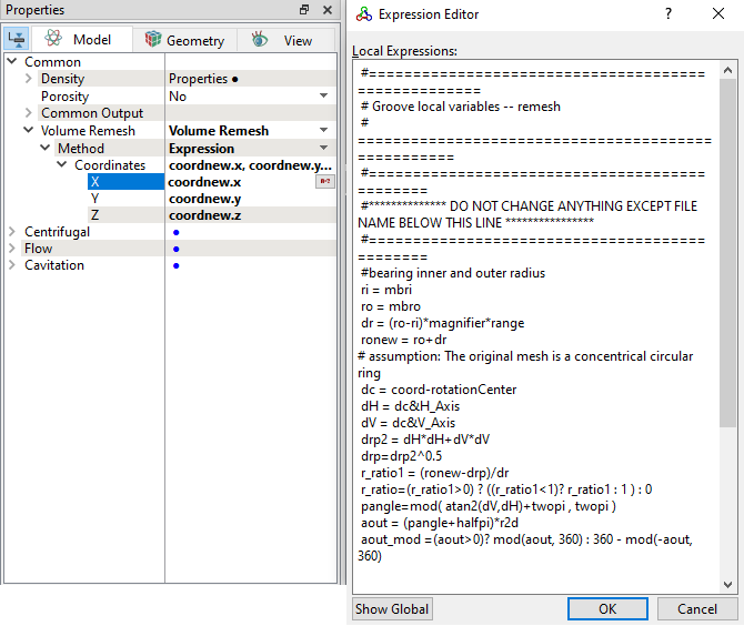
Groove Local Expression
#==================================================== # Groove local variables -- remesh # =================================================== #============================================== #************** DO NOT CHANGE ANYTHING EXCEPT FILE NAME BELOW THIS LINE **************** #============================================== #bearing inner and outer radius ri = mbri ro = mbro dr = (ro-ri)*magnifier*range ronew = ro+dr # assumption: The original mesh is a concentrical circular ring dc = coord-rotationCenter dH = dc&H_Axis dV = dc&V_Axis drp2 = dH*dH+dV*dV drp=drp2^0.5 r_ratio1 = (ronew-drp)/dr r_ratio=(r_ratio1>0) ? ((r_ratio1<1)? r_ratio1 : 1 ) : 0 pangle=mod( atan2(dV,dH)+twopi , twopi ) aout = (pangle+halfpi)*r2d aout_mod =(aout>0)? mod(aout, 360) : 360 - mod(-aout, 360) rin = ri rout1 = table("Mainbearing_distorted.txt", aout_mod)/1000 #File unit is in mm rout=rin+(rout1-rin)*magnifier rnew = drp + (rout-ro)*r_ratio coordnew = rnew*cos(pangle)*H_Axis+rnew*sin(pangle)*V_Axis +(coord&rotationAxis)*rotationAxis
|
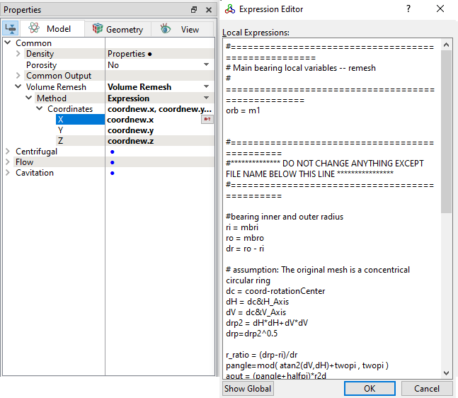
Shaft Bearing Local Expression
#==================================================== # Main bearing local variables -- remesh # =================================================== orb = m1 #============================================== #************** DO NOT CHANGE ANYTHING EXCEPT FILE NAME BELOW THIS LINE **************** #============================================== #bearing inner and outer radius ri = mbri ro = mbro dr = ro - ri # assumption: The original mesh is a concentrical circular ring dc = coord-rotationCenter dH = dc&H_Axis dV = dc&V_Axis drp2 = dH*dH+dV*dV drp=drp2^0.5 r_ratio = (drp-ri)/dr pangle=mod( atan2(dV,dH)+twopi , twopi ) aout = (pangle+halfpi)*r2d aout_mod =(aout>0)? mod(aout, 360) : 360 - mod(-aout, 360) rin = ri rout1 = table("Mainbearing_distorted.txt", aout_mod)/1000 #File unit is in mm rout=rin+(rout1-rin)*magnifier # calculate inner radius considering orbiting of the inner surface (still a circle), to get # more orthogonal mesh aa = drp2 bb = dc&orb cc = rin^2-(orb.y^2 +orb.x^2+orb.z^2) rin1 = (bb + (bb^2 + aa*cc)^0.5)/drp dr1=rout-rin1 rin2=(dr1<epsmin)?rout-epsmin:rin1 rnew = rin2 + (rout-rin2)*r_ratio coordnew = rnew*cos(pangle)*H_Axis+rnew*sin(pangle)*V_Axis+(coord&rotationAxis)*rotationAxis
|
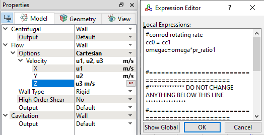
Conrod outer velocity
|
The orbit and deformation data are obtained from a separate Finite Element Analysis (FEA) of the bearing structure.
From the FEA raw data, convert orbit and deformation data into Simerics input file format. The following input files are prepared for main bearing and conrod bearings and placed in the tutorial case file folder.
Ensure to copy following input text files in the same folder of project file.