Building the mesh
This section describes the step-by-step procedure to prepare the mesh for the coolant filling system model that contains tank, battery pack, radiator, pump, coolant pipe and vent pipe. The mesh is created using the General Mesher and Template Mesher.
Battery pack
- Select all CAD Surfaces for battery packs (names with battery_) in the Geometric Entities Panel.
- Select General Mesher in the Mesh Panel.
- Enter Maximum Cell Size = 0.001, Minimum Cell Size = 0.0001 and Cell Size on Surfaces = 0.001 and Cell Size Specification as Absolute in the Properties Panel.
- Click Create Mesh. A new mesh battery_pack is created under Built Meshes and Volumes in the Geometric Entities Panel.
Tank
- Select all CAD Surfaces for tank (names with tank_) in the Geometric Entities Panel.
- Select General Mesher in the Mesh Panel.
- Enter Maximum Cell Size = 0.0015, Minimum Cell Size = 0.0001 and Cell Size on Surfaces = 0.0015 and Cell Size Specification as Absolute in the Properties Panel.
- Click Create Mesh. A new mesh tank is created under Built Meshes and Volumes in the Geometric Entities Panel.
Pump - Rotor
- Select all CAD Surfaces for rotor (names with rotor_ in the Geometric Entities Panel and enter Mesh Name as rotor_.
- Select General Mesher in the Mesh Panel.
- Enter Maximum Cell Size = 0.001, Minimum Cell Size = 0.0001, Cell Size on Surfaces = 0.001 and Cell Size Specification as Absolute in the Properties Panel. Select Volume Options as Multiple Volumes.
- Click Create Mesh. A new mesh rotor_ is created under Built Meshes and the meshed volume rotor is generated under Volumes in the Geometric Entities Panel.
Pump - Volute
- Select all CAD Surfaces for volute (names with volute_) in the Geometric Entities Panel and enter Mesh Name as volute.
- Select General Mesher in the Mesh Panel.
- Enter Maximum Cell Size = 0.001, Minimum Cell Size = 0.0001, Cell Size on Surfaces = 0.001 and Cell Size Specification as Absolute in the Properties Panel. Select Volume Options as Multiple Volumes.
- Click Create Mesh. A new mesh volute is created under Built Meshes and the meshed volume volute is generated under Volumes in the Geometric Entities Panel.
Coolant pipe
- Select all CAD Surfaces for coolant pipe (names with pipe_) in the Geometric Entities Panel.
- Select General Mesher in the Mesh Panel.
- Enter Maximum Cell Size = 0.001, Minimum Cell Size = 0.0001, Cell Size on Surfaces = 0.001 and Cell Size Specification as Absolute in the Properties Panel. Select Volume Options as Single Volume.
- Click Create Mesh. A new mesh pipe is created under Built Meshes and Volumes in the Geometric Entities Panel.
Vent
- Select all CAD Surfaces for vent (names with vent_) in the Geometric Entities Panel.
- Select General Mesher in the Mesh Panel.
- Enter Maximum Cell Size = 0.001, Minimum Cell Size = 0.0001, Cell Size on Surfaces = 0.001 and Cell Size Specification as Absolute in the Properties Panel. Select Volume Options as Single Volume.
- Click Create Mesh. A new mesh vent is created under Built Meshes and Volumes in the Geometric Entities Panel.
Headers
- Select all CAD Surfaces for headers (names with header1 and header2) in the Geometric Entities Panel and enter Mesh Name as headers.
- Select General Mesher in the Mesh Panel.
- Enter Maximum Cell Size = 0.001, Minimum Cell Size = 0.0003, Cell Size on Surfaces = 0.001 and Cell Size Specification as Absolute in the Properties Panel. Select Volume Options as Multiple Volumes.
- Click Create Mesh. A new mesh headers is created under Built Meshes and header1 and header2 are generated under Volumes in the Geometric Entities Panel.
Tubes
|
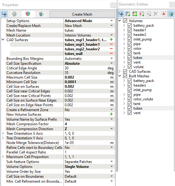
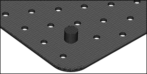
Figure 17.55 - Battery pack |
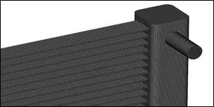
Figure 17.56 - Radiator |
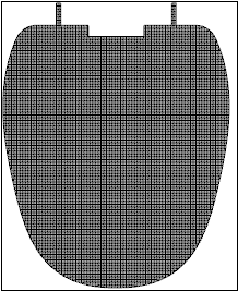
Figure 17.57 - Tank |
Create interfaces
In this section, the Mismatched Grid Interfaces (MGIs) are generated between the following boundaries.
The steps to create the MGI are as follows:
- Geometric Entities Panel > Volumes > Boundaries, select entities under Boundaries as shown in Table 17.4.
- Click Connect Selected Boundaries via MGI
 icon to create the MGI entities.
A group display of entities can be viewed using the Group Entities by Volumes/Types![]() icon in Geometric Entities Panel toolbar. Following are the (MGIs) to be created with corresponding boundaries, as shown in Table 17.4.
icon in Geometric Entities Panel toolbar. Following are the (MGIs) to be created with corresponding boundaries, as shown in Table 17.4.
Interfaces
| Connecting interfaces | Boundaries | Entity |
|---|---|---|
| Battery Pack and Pipe | battery_pack_inlet_mgi1_pipe and pipe_mgi6_battery_pack_inlet | MGI01 |
| Battery Pack and Pipe | battery_pack_outlet_mgi2_pipe and pipe_mgi5_battery_pack_outlet | MGI02 |
| Header1 and Pipe | header1_mgi2_pipe and pipe_mgi2_header1 | MGI03 |
| Header2 and Pipe | header2_mgi2_pipe and pipe_mgi4_header2 | MGI04 |
| Header1 and tubes | header1_mgi1_tubes and tubes_mgi1_header1 | MGI05 |
| Header2 and tubes | header2_mgi1_tubes and tubes_mgi2_header2 | MGI06 |
| Tank and Pipe | tank_mgi1_pipe and pipe_mgi8_tank | MGI07 |
| Tank and Vent_pipe | tank_mgi2_vent_pipe and vent_mgi3_tank | MGI08 |
| Tank and Vent_pipe | tank_mgi3_vent_pipe and vent_mgi1_tank | MGI09 |
| Rotor and Pipe | rotor_inlet_mgi_pipeand pipe_mgi7_rotor_inlet | MGI10 |
| Vent_pipe and Pipe | vent_mgi2_pipeand pipe_mgi1_vent_pipe | MGI11 |
| Vent_pipe and Header2 | vent_mgi4_header2 and header2_mgi3_vent_pipe | MGI12 |
| Volute and Pipe | volute_outlet_mgi_pipe and pipe_mgi3_volute_outlet | MGI13 |
| Rotor and Volute | rotor_mgi_volute and volute_mgi_rotor | MGI14 |
Table 17.4 - Creating interfaces
| ´ | Note: If MGIs are created by connecting the wrong Boundaries, delete the created MGIs by clicking on Delete Selected Geometric Entity |