Defining physics and conditions
The physics and conditions are specified as follows.
a) Adding modules
- Click Select Modules in the Model Panel. The Physical Model Selection dialog box opens.
- Select Multiphase and Turbulence in the Available Modules list, click Add.
-
Click Close, to close the Physical Model Selection dialog box.
|
|
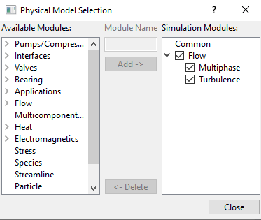
Figure 17.78 - Adding modules
|
Common
- Select Common in the Model Panel.
- Select Transient from the Time Definition drop-down list in the Model Panel of Properties Panel.
- Enter Number of Iterations = 10.
- Enter Simulation Time (Duration) = 250 s and Number of Time Steps = 25000 for the Time Definition list.
-
Enter Result Saving Frequency = 100.
|
|
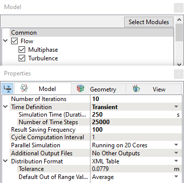
Figure 17.79 - Common operating parameters
|
Flow
- Select Flow in the Model Panel.
- Select 2nd Order Upwind for Velocity and Upwind for Pressure in the Numeric Scheme drop-down list.
- Enter Velocity = 0.1 and Pressure = 0.001 in the Linear Solver Tolerance drop-down list.
- Select Yes for Gravity Force drop-down list.
- Enter g = 0, 0, -9.81 m/s2 in the Gravity Force list.
- Enter Max. Velocity Magnitude = 200 m/s.
|
|
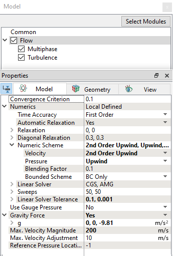
Figure 17.80 - Flow operating parameters
|
Multiphase
- Select Multiphase in the Model Panel.
- Click two times Add Element
 icon for Components in the Model Tab of Properties Panel, to add components. icon for Components in the Model Tab of Properties Panel, to add components.
- Rename comp_1 and comp_2 as coolant and air respectively.
-
Enter Compression Factor = 100 under Numeric Scheme drop-down list.
|
|
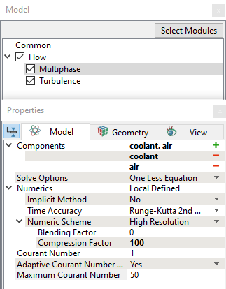
Figure 17.81 - Multiphase operating parameters
|
b) Boundary conditions
The inlet flow to the tank is given through a user expression based on minimum and maximum level of the tank. The pump speed is also changed in the expression depending on gravity or pump-on filling processes.
Reference for Global expressions and image with call outs are shown in Figure 17.82.
Global Expression
- Click Edit Expression
 icon on the View Toolbar to open the Expression Editor dialog box. icon on the View Toolbar to open the Expression Editor dialog box.
-
Copy and paste the expressions written under Description drop-down list for Global Expressions, see Figure 17.82.
 Description Description
pump_speed = 3000 #rpm
vol_tank = integral((phasecomp.coolant.vFrac>=0.5)?1:0,volume.tank)
value = 2.0 #L/min
vol_col_tank = vol_tank
v_max = 0.00095737 #m^3
v_min = 0.000273 #m^3
plot.vol_col_tank=vol_col_tank
q_in = (time==0)?0:abs(flow.q@tank_coolant_inlet)
plot.q_in = q_in
switch = (vol_col_tank <= v_min)?1:(((vol_col_tank >= v_min) and (vol_col_tank <= v_max) and (q_in > 0.005))?1:(vol_col_tank >= v_max)?0:((vol_col_tank >= v_min) and (vol_col_tank <= v_max) and (q_in <= 0.005))?0:1)
plot.switch = switch
flow_in = (switch == 1) ? value : 0
plot.flow_in = flow_in
- Click OK to close the Expression Editor dialog box.
|
|
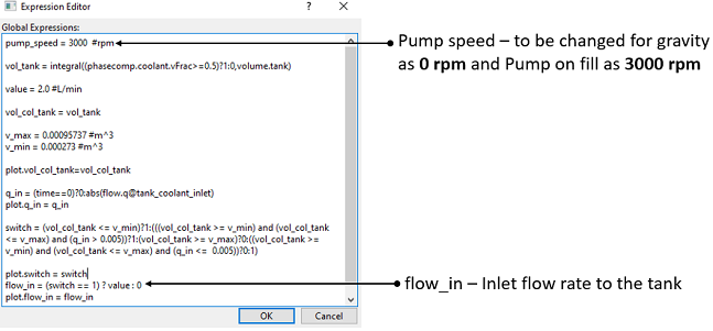
Figure 17.82 - Global Expression
|
Inlet
- Select tank_coolant_inlet from the Boundaries list in the Geometric Entities Panel.
- Select Specified Volumetric Flux for the Flow drop-down list in the Model Tab of Properties Panel.
- Enter flow_in L/min for Value under the Flow drop-down list (reference to the script see, Figure 17.83.
- Enter Value = 1 in the Component coolant list and Value = 0 in the Component air list under Multiphase drop-down list.
- Select User Select for the Output drop-down list and select Yes for the Mass Flux and Volumetric Flux in the Component coolant and Component air drop-down list.
|
|
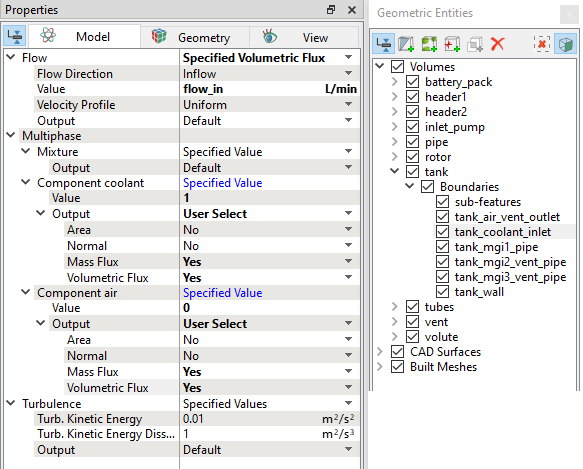
Figure 17.83 - Inlet conditions
|
Outlet
- Select tank_air_vent_outlet from the Boundaries list under Volumes in the Geometric Entities Panel.
- Select Specified Pressure Outlet under Flow drop-down list in the Model Tab of Properties Panel.
- Verify that the Pressure = 101325 Pa under the Flow .
- Enter Value = 0 in the Component coolant list and Value = 1 in the Component air list under Multiphase drop-down list.
- Select User Select for the Output drop-down list and select Yes for the Mass Flux and Volumetric Flux in Component coolant and Component air drop-down list.
|
|
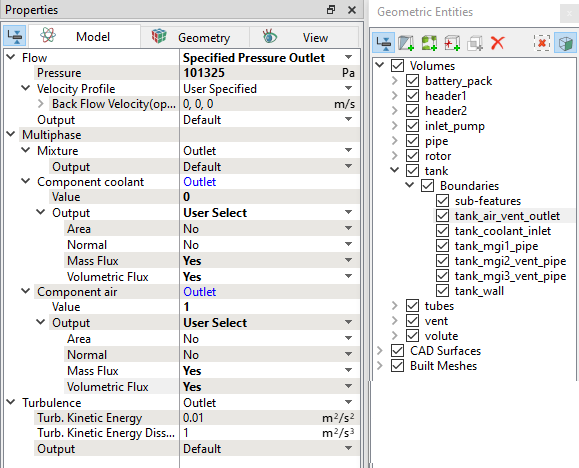
Figure 17.84 - Outlet conditions
|
Rotor conditions
Non-inertial frame of approach is used to model impeller rotation.
- Select rotor from Volumes in the Geometric Entities Panel.
- Select Noninertial Frame from the Noninertial Frame drop-down list under Flow under Mixture in the Properties Panel as shown in the Figure 17.85.
-
Enter the following under Noninertial Frame list.
-
Rotational Direction: Clockwise
- Rotational Speed: pump_speed rpm
- Rotational Center: -0.012822, -9.4e-07, -0.33279781 m
-
Rotational Axis Vector: 1, 0, 0
- Select rotor and volute_rotating_wall from the Boundaries drop-down list under volute in the Properties Panel.
- Select Rotating_Wall under Mixture drop-down list in the Model Tab of Properties Panel.
-
Enter the conditions mentioned above in step 3, under Mixture in the Properties Panel as shown in the Figure 17.86.
|
|
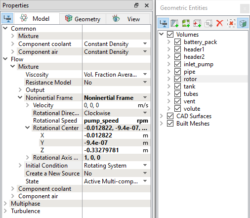
Figure 17.85 - Rotor volume conditions
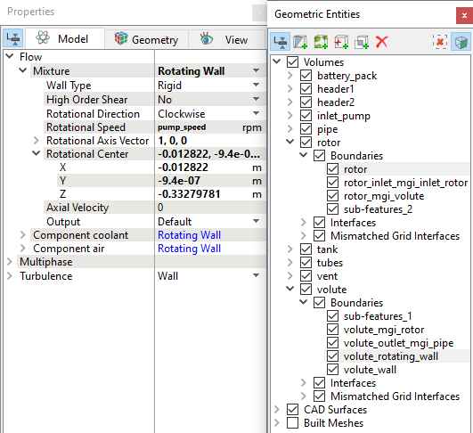
Figure 17.86 - Rotor and Volute rotating wall boundary conditions
|
c) Fluid properties
- Select Volumes in the Geometric Entities Panel.
- Select Model Tab in the Properties Panel.
- Enter the Value = 998 kg/m3 under Component coolant for the Common list in the Model Tab of Properties Panel.
- Enter the Value = 1.1766 kg/m3 under Component air for the Common list in the Model Tab of Properties Panel.
- Enter the Value = 0.001003 Pa-s under Viscosity in Component coolant in the Flow list.
- Enter the Value = 0.072 N/m under Surface Tension in Component coolant in the Flow list.
- Enter the Value = 1.853e-05 Pa-s under Viscosity in Component air in the Flow list.
- Enter the Value = 0 under Initial Condition in Component coolant and Value = 1under Initial Condition in Component air in the Multiphase list.
| ´ |
Note: Select Yes for Volume, Mass Fraction, Volume Fraction , Phase Mass and Phase Volume under Component Output list for the Component coolant and Component air list. |
|
|
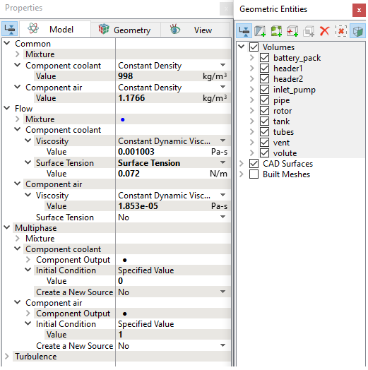
Figure 17.87 - Fluid properties
|
d) Operating conditions
The coolant filling system simulation is performed in two steps. In the first step, gravity filling simulation is up to 250 s and in second step, pump-on filling is simulated up to 360 s continued from the results of gravity filling.
Under the operating conditions, specify the pump speed as follows:
-
Gravity Fill: For gravity fill, change the pump speed to 0 rpm. (Refer to Figure 17.82).
- Pump-on Fill: For pump-on fill, change the pump speed to 3000 rpm. (Refer to Figure 17.82).