中文 English

Computational domain

This section explains the preparation of surfaces to create the domain. This is done with the operations splitting, combining and renaming of the surfaces.

Piston Cooling Surfaces
  1. Select CAD Surfaces pistoncooling_fluid in the Geometric Entities Panel.
  2. Select Split/Combine Geometry or Grid in the Mesh Panel.
  3. Select Split Disconnected from the Operation drop-down list in the Properties Panel, click Split Disconnected. Three new CAD Surfaces are created in the Geometric Entities Panel.
  4. Rename the CAD Surfaces pistoncooling_fluid_01 as pistonfluid, pistoncooling_fluid_02 as cylinder_outer and pistoncooling_fluid_03 as nozzle.

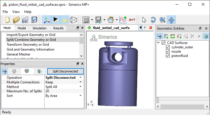
Figure 7.223 - Split of CAD surfaces

Nozzle Surfaces
  1. Select CAD Surfaces nozzle in the Geometric Entities Panel.
  2. Select Split by Angle from the Operation drop-down list in the Properties Panel.
  3. Enter 50 deg for Angle, click Split by Angle. Five new CAD Surfaces are created in the Geometric Entities Panel.
  4. Select CAD Surfaces nozzle_03, nozzle_04 and rename as nozzle_inlet, nozzle_mgi respectively.
  5. Select CAD Surfaces nozzle_01, nozzle_02 and nozzle_05.
  6. Select Combine from the Operation drop-down list in the Properties Panel, click Combine and rename as nozzle_wall.
 

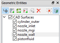
Figure 7.224 - Nozzle surfaces

Piston Fluid Surfaces
  1. Select CAD Surfaces pistonfluid in the Geometric Entities Panel.
  2. Select Split by Angle from the Operation drop-down list in the Properties Panel.
  3. Enter 20 deg for Angle and 4 for Maximum No. of Splits, click Split by Angle. Five new CAD Surfaces are created in the Geometric Entities Panel.
  4. Select CAD Surfaces pistonfluid_02, pistonfluid_03, pistonfluid_04 and rename as pistonfluid_mgi, pistonfluid_gallerypistonfluid_others respectively.
  5. Select CAD Surfaces pistonfluid and pistonfluid_01.
  6. Select Combine from the Operation drop-down list in the Properties Panel, click Combine.
 

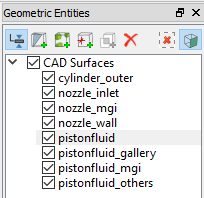
Figure 7.225 - Piston Fluid surfaces


Copyright © 2023 Simerics Inc.,