- Select Piston Cooling Template Mesher in the Mesh Panel.
- Enter the parameters as follows:
- Piston Motion Direction: 0,0,1
- Jet Direction: 0,0,1
- Con-Rod Length: 0.11
- Crank Radius: 0.036924
- Enter -0.135,0,0 m for Gallery Ring Center under Gallery.
- Select CAD Surfaces pistonfluid_gallery in the Geometric Entities Panel and click Add Surfaces
 icon next to Gallery Surfaces in the Properties Panel. icon next to Gallery Surfaces in the Properties Panel.
- Select CAD Surfaces pistonfluid, click Add Surfaces icon next to Piston UnderCrown Surfaces. Select CAD Surfaces pistonfluid_mgi, click Add Surfaces icon next to Piston Cylinder MGI Surfaces. Similarly select CAD Surfaces pistonfluid_others, click Add Surfaces icon next to Other Piston Surfaces.
- Select CAD Surfaces nozzle_inlet, click Add Surfaces icon next to Inlet Surface. Select CAD Surfaces nozzle_mgi, click Add Surfaces icon next to Nozzle Cylinder MGI Surface. Similarly, select CAD Surfaces nozzle_wall, click Add Surfaces icon next to Nozzle Walls.
- Select CAD Surfaces cylinder_outer in the Geometric Entities Panel, click Add Surfaces icon next to Cylinder Surface in the Properties Panel.
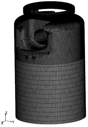
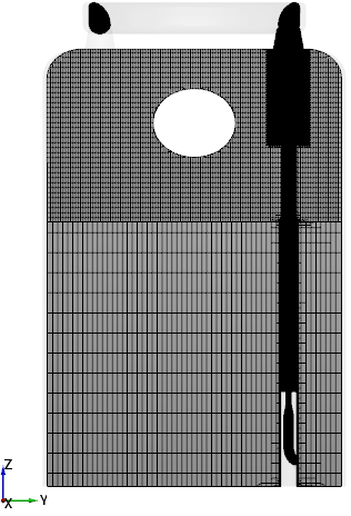
- Click Build Piston Cooling. The new mesh piston is created under Built Meshes in the Geometric Entities Panel.
- The meshed volumes cylinder, gallery, jet, nozzle and piston_fluid are generated under Volumes.
|
|
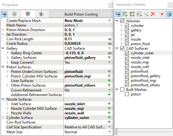
Figure 7.226 - Piston fluid mesh settings
|