中文 English
You are here: Automotive Templates and Tutorials > Automotive Tutorials > Piston Cooling Tutorial > Defining Physics and Conditions

Defining Physics and Conditions

The physics and conditions are specified as follows:

Adding Modules
  1. Click Select Modules in the Model Panel. The Physical Model Selection dialog box opens.
  2. Select Piston Cooling under Available Modules list and click Add.
  3. Click Close to close the Physical Model Selection dialog box.


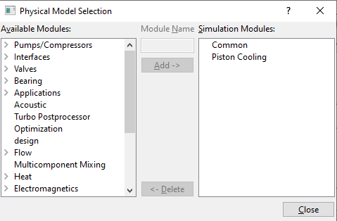
Figure 7.243 - Adding modules

Operating Parameters
Piston Cooling
  1. Select Piston Cooling in the Model Panel.
  2. Select Solid from the Simulation Type drop-down list in the Model Tab of Properties Panel.
  3. Enter 0.11 m for Con-Rod Length.
  4. Enter 0.036924 m for Crank Radius.
  5. Enter 0,0,1 for Piston Motion Direction.
  6. Select Yes from the Coupled with Fluid drop-down list in the Model Tab of Properties Panel. Heat and Data Exchange PistonCooling modules are automatically added to the Model Panel.
  7. Enter piston_fluid.spro for Fluid Project File.
 

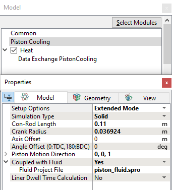
Figure 7.244 - Piston Cooling operating parameters


Heat
  1. Select Heat in the Model Panel.
  2. Enter 1e-06 for Convergence Criterion.
 

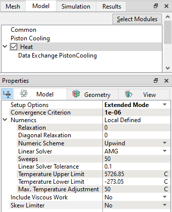
Figure 7.245 - Heat operating parameters


Boundary Conditions

The boundary conditions are specified as follows:

Piston Top
  1. Select piston_top from the Boundaries list in the Geometric Entities Panel.
  2. Select Specified Total Heat Flux from the Heat drop-down list in the Model Tab of Properties Panel.
  3. Enter 3000 W for Value.
 

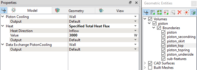
Figure 7.246 - Piston top conditions

Piston Rings
  1. Select piston_topring from the Boundaries list in the Geometric Entities Panel.
  2. Select Specified Temperature from the Heat drop-down list in the Model Tab of Properties Panel.
  3. Enter 130 C under Temperature.
  4. Select User Select for Output drop-down list under Heat and select Yes for Total Flux.
  5. Select piston_secondring from the Boundaries list in the Geometric Entities Panel.
  6. Select Specified Temperature from the Heat drop-down list in the Model Tab of Properties Panel.
  7. Enter 120 C under Temperature.
  8. Select User Select for Output drop-down list under Heat and select Yes for Total Flux.
 

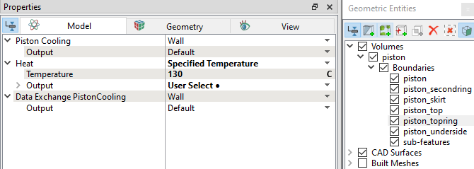
Figure 7.247 - Piston topring conditions


Figure 7.248 - Piston secondring conditions

Piston Skirt
  1. Select piston_skirt from the Boundaries list in the Geometric Entities Panel.
  2. Select Specified Temperature from the Heat drop-down list in the Model Tab of Properties Panel.
  3. Enter 110 C under Temperature.
  4. Select User Select for Output drop-down list under Heat and select Yes for Total Flux.
 

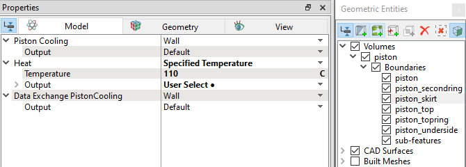
Figure 7.249 - Piston skirt conditions


Piston Underside
  1. Select piston_underside from the Boundaries list in the Geometric Entities Panel.
  2. Select Fluid Interface from the Piston Cooling drop-down list in the Model Tab of Properties Panel.
  3. Enter 40 K for Max Temperature Change.
 

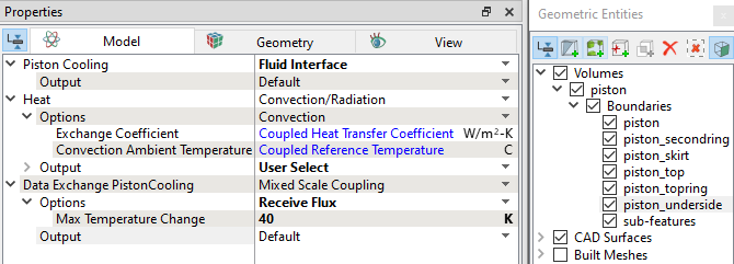
Figure 7.250 - Piston underside conditions


´ Note:  piston_underside boundary is the corresponding mapping surface in the solid model.


Solid Properties
  1. Select Volumes in the Geometric Entities Panel.
  2. Enter 2700 kg/m3 for Valve under the Density drop-down list in the Model Tab of Properties Panel.
  3. Enter 130 W/m-K for Conductivity under Heat.
  4. Enter 900 J/kg-K for Capacity under Heat.
 

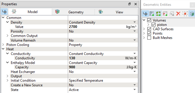
Figure 7.251 - Solid properties


Copyright © 2023 Simerics Inc.,