中文 English
You are here: Automotive Templates and Tutorials > Automotive Tutorials > Piston Cooling Tutorial > Defining Physics and Conditions

Defining Physics and Conditions

Physical Modules
  1. The physical modules Piston Cooling, Multiphase, Turbulence and Heat modules are automatically added to the Model Panel by the Piston Cooling Template Mesher.
 

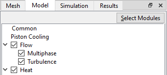
Figure 7.229 - Physical modules


Operating Parameters
Common
  1. Select Common in the Model Panel.
  2. Enter 720 for Cycle Computational Interval.
 

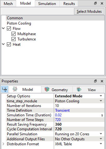
Figure 7.230 - Common operating parameters
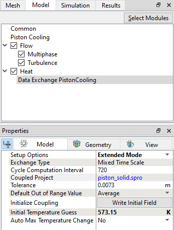
 

Piston Cooling
  1. Select Piston Cooling in the Model Panel.
  2. Select Fluid from the Simulation Type drop-down list in the Model Tab of Properties Panel.
  3. Enter 3000 rpm for Engine Speed.
  4. Select Yes from the Coupled with Solid drop-down list in the Model Tab of Properties Panel. Data Exchange PistonCooling module is automatically added to Model Panel.
  5. Enter piston_solid.spro for Solid Project File.
 

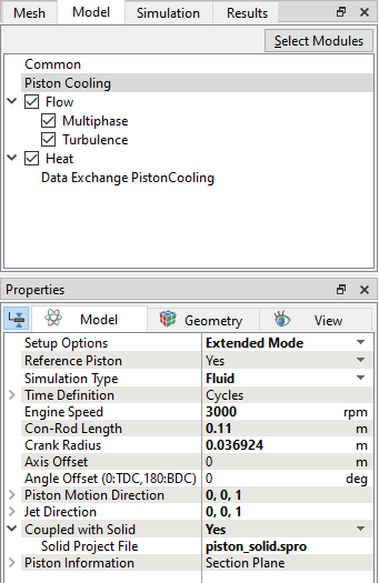
Figure 7.231 - Piston Cooling operating parameters


Data Exchange
  1. Select Data Exchange PistonCooling in the Model Panel.
  2. Enter 573.15 K for Initial Temperature Guess.
  3. Click Write Initial Field next to Initialize Coupling parameter in the Model Tab of Properties Panel to automatically write an initial temperature file with the name piston_solid_piston_cooling_temperature.txt in the working directory. Click Continue in the Warning dialog box, see Figure 7.233.
 

Figure 7.232 - Data Exchange PistonCooling operating parameters


Figure 7.233 - Piston Cooling Warning dialog


  Note: All the other operating parameters for Flow, Multiphase and Heat models are automatically set by the template.
Boundary Conditions

The boundary conditions are specified as follows:

Inlet
  1. Select nozzle_inlet from the Boundaries list in the Geometric Entities Panel.
  2. Enter 4e-05 m3/s for Value under the Flow drop-down list.
  3. Verify that the Value in the Component oil list under the Multiphase is 1.
  4. Verify that the Value in the Component air list under the Multiphase is 0.
  5. Select User Select for Output drop-down list in Component oil.
  6. Select Yes for Mass Flux in Component oil drop-down list.
  7. Enter 373.15 K for Temperature under the Heat drop-down list.
 

Figure 7.234 - Nozzle inlet conditions


Outlet
  1. Select cylinder_bot from the Boundaries list in the Geometric Entities Panel.
  2. Verify that the Pressure under the Flow is 101325 Pa.
  3. Verify that the Value in the Component oil list under the Multiphase is 0.
  4. Verify that the Value in the Component air list under the Multiphase is 1.
  5. Select User Select for Output drop-down list in Component oil and Component air.
  6. Select Yes for Mass Flux and Volumetric Flux in Component oil and Component air drop-down list.
  7. Enter 373.15 K for Temperature under the Heat drop-down list.
 

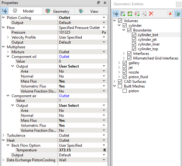
Figure 7.235 - Outlet conditions

  Note: The mapping boundaries gallery_wall and piston_fluid_wall are automatically set to the Specified Temperature boundary condition by the template.
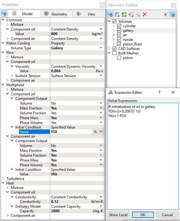
Fluid Properties
  1. Select Volumes in the Geometric Entities Panel.
  2. Enter 800 kg/m3 for Value under Component oil for the Common list in the Model Tab of Properties Panel.
  3. Enter 0.004 Pa-s for Value under Viscosity in Component oil in the Flow list.
  4. Select Surface Tension under Surface Tension drop-down list in the Flow list.
  5. Enter 0.12 W/m-K under Conductivity and 2800 J/kg-K under Capacity in Component oil in the Heat list.
 

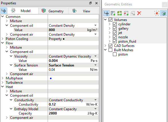
Figure 7.236 - Fluid properties

Initial Conditions
  1. Select gallery from the Volumes list in the Geometric Entities Panel.
  2. Click Edit Expressions icon on the Toolbar or in the Value under Initial Condition for Component oil and Component air drop-down list, to open the Expression Editor dialog box.
  3. Enter the following for Global Expressions, (see Figure 7.237).
    fOil = (z<0.2067) ? 1 : 0
    fAir = 1 - fOil
  4. Click OK, to close the Expression Editor dialog box.
  5. Enter fOil in the Value under Initial Condition in the Component oil list.
  6. Enter fAir in the Value under Initial Condition in the Component air list.
  7. Select Yes for Mass Fraction, Volume Fraction, Phase Mass, and Phase Volume under Component Output list for the Component oil.
 

Figure 7.237 - Gallery Initial condition


Copyright © 2023 Simerics Inc.,