|
You are here: Automotive Templates and Tutorials > Automotive Tutorials > Water Wading Tutorial > Plots
|
Plots
This section shows some of the common plots used in the water wading simulation. The steps to create the plots are:
- Click Load Results in the Simulation Panel.
- Select the required result file in the ensuing Load Results dialog box, click Open.
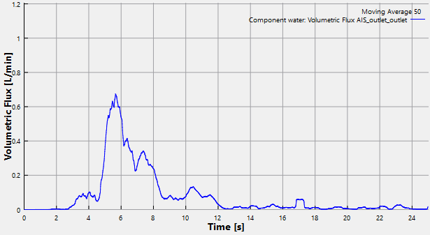
Water inducted in air induction system
- Select AIS_outlet_outlet under Boundaries in the Geometric Entities Panel.
- Click Add XY-Plot
 icon in the Toolbar.
 - Click Click for Variable List
 icon and select Volumetric Flux under Component water list in the Plot Panel.
 - Select Plot Selected Variables
 icon.
icon. - Click Plot Property
 icon, the Plot Property dialog box opens. Enable Moving Average and enter 50.
 - Select L/min for Unit under Display Units and click OK.
| ´ | Note: The moving average is used in transient simulations to obtain the average behavior over the entire simulation time. It can be specified as, click Click for Variable List |
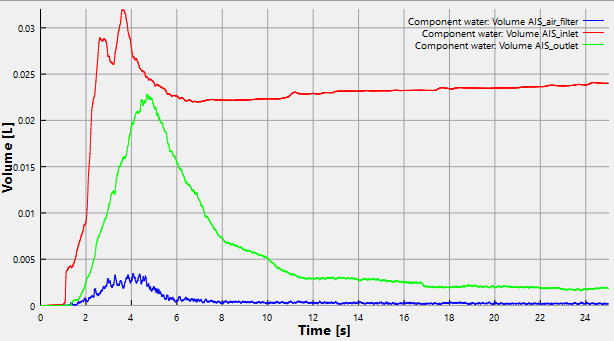
Volume of water in AIS inlet, AIS outlet and AIS air filter
- Select AIS_inlet, AIS_outlet and AIS_air_filter under Volumes in the Geometric Entities Panel.
- Click Add XY-Plot icon in the Toolbar.
- Click Click for Variable List icon and and select Volume from Component water list in the Plot Panel.
- Click Plot Selected Variables icon.
- Click Plot Property icon, the Plot Property dialog box opens.
- Select L for Unit under Display Units and click OK.
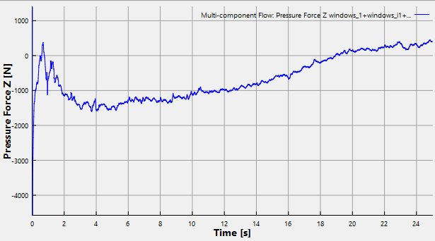
Pressure force in z-direction
- Select all Boundaries in the Geometric Entities Panel, except the boundaries with prefix vehicle and wheel and AIS_outlet_outlet.
- Click Add XY-Plot icon in the Toolbar.
- Click Click for Variable List icon and select Pressure Force Z from Multi-component Flow list in the Plot Panel.
- Click Combine Entity Data into a Single Curve
 icon to obtain the net pressure force in X direction.