Building the Mesh
This section describes the step-by-step procedure for preparing the mesh for the windshield defrost simulation. The General Mesher is used for creating the mesh for the car and the Template Mesh/Surface is used for creating the mesh for windshield and iceVolume.
Car Mesh
- Select General Mesher in the Mesh Panel.
- Enter car under Mesh Name in the Properties Panel.
- Select all CAD Surfaces in the Geometric Entities Panel and click Add Surfaces
 icon for CAD Surfaces in the Properties Panel. icon for CAD Surfaces in the Properties Panel.
- Enter the Maximum Cell Size as 0.01, Minimum Cell Size as 0.0007 and Cell Size on Surfaces as 0.01 .
- Click Create Mesh. A new mesh car is created under Built Meshes in the Geometric Entities Panel.
- The meshed Volume car is generated under Volumes.
|
|
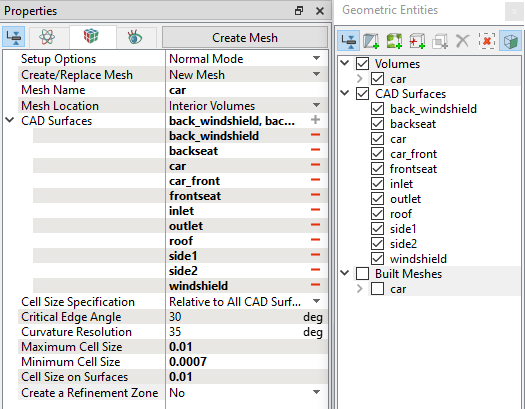
Figure 7.268 - Car mesh settings
|
Windshield Mesh
|
To generate a mesh for windshield and ice Volume, the Layer option is used.
- Select Template Mesh/Surface in the Mesh Panel.
- Select Layer from the Shape drop-down list in Geometry Tab of Properties Panel.
- Enter windshield for Mesh Name.
- Select windshield from the Boundaries list under car Volume in the Geometric Entities Panel.
- Click Add Surfaces icon for Surfaces in the Properties Panel.
-
Enter the parameters as follows:
- Thickness: 0.005 m
- Cell Size on Wall: 0.00025 m
- Number of Layers: 20 under Cluster Options for Exponential
- Click Build Layer Mesh. The new mesh windshield is created under Built Meshes in the Geometric Entities Panel.
- The meshed volumes windshield is generated under Volumes.
|
|
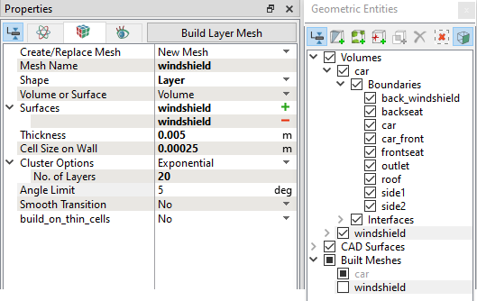
Figure 7.269 - Windshield mesh settings
|
Ice Mesh
|
To generate a mesh for ice Volume, the Layer option is used.
- Select Template Mesh/Surface in the Mesh Panel.
- Select Layer from the Shape drop-down list in Geometry Tab of Properties Panel.
- Enter ice for Mesh Name.
- Select windshield_top from the Boundaries list under windshield Volume in the Geometric Entities Panel.
- Click Add Surfaces icon for Surfaces in the Properties Panel.
-
Enter the parameters as follows:
- Thickness: 0.001 m
- Cell Size on Wall: 0.00025 m
- Number of Layers: 4 under Cluster Options for Exponential
- Select Yes for build_on_thin_cells drop-down
- Click Build Layer Mesh. The new mesh ice is created under Built Meshes in the Geometric Entities Panel.
- The meshed volume ice is generated under Volumes.
|
|
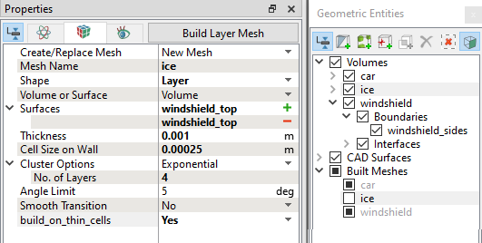
Figure 7.270 - Ice mesh settings
|
The mesh created for the fluid domain is shown below.
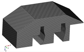
Figure 7.271 - Car mesh
|
|
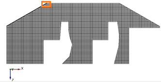
Figure 7.272 - Sectional view (Y=0)
|
|
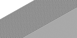
Figure 7.273 - Zoomed view at windshield and ice mesh
|
Default Interfaces
Interfaces are automatically created between the volumes.
|
|
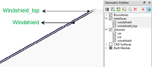
Figure 7.274 - Default interfaces
|
Seperate interface
- Select inlet from the Interfaces list under car Volume in the Geometric Entities Panel.
- Select Split/Combine Geometry or Grid under Mesh Panel.
- Select Separate Interface under Operation drop-down list in the Properties Panel.
- Click Separate Interface. Two new Boundaries inlet_i1 and inlet_i2 are created under Boundaries list of car Volume.
|
|
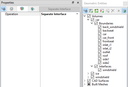
Figure 7.275 - Separate inlet interface
|