7.2.1 Geometry and Domain
The fuel tank simulations require understanding of the geometry and fluid volume enclosed by the surfaces. The main parts of the fuel tank are shown in Figure 7.76
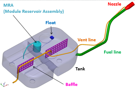
In case of fuel tank filling: The geometry consist of Nozzle, Fuel line, Vent line, Tank and Baffles as shown in the Figure 7.76. With Fuel Tank Template Mesher, valve such as flip valve and spool valve are automatically created. A valve is placed at the entrance of the storage tank, which allows the filling of tank when there is a pressure in the fuel flow. And also, avoids the reverse flow of the fuel from the tank to the inlet, when the vehicle is moving.
In case of fuel sloshing: The geometry consist of Tank, Float and Baffles as shown in the Figure 7.76 The Fuel Tank Template Mesher generates customized mesh around the float and to its maximum and minimum displacements.
Pre-requisite steps for Tank Refueling
- For tank and fuel line an opening is needed, where the tank is connected with the fuel line. The size of the opening on the fuel line does not have to match with the opening on the tank. But the two openings need to be in the same plane.
- For both Nozzle and Vent line, the CAD Surfaces representing those two volumes should be closed volumes.
Pre-requisite steps for Sloshing
- Tank surface has to be water-tight.
- The float’s two rotational axis are assumed to be parallel with each other.
- You can add multiple floats, which can have different rotational axis of their own.
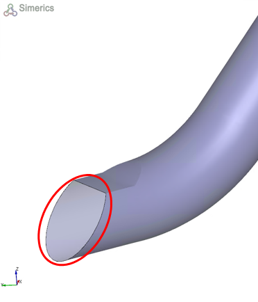
Figure 7.77 - Fuel line opening |
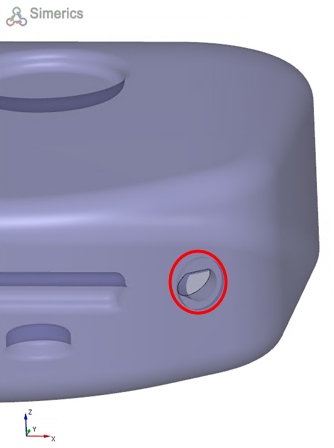
Figure 7.78 - Tank opening |
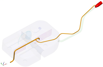
Figure 7.79 - Nozzle and Vent line |