|
You are here: Fluid Machinery Templates and Tutorials > Ball Valve > Ball 3D Valve Tutorial > Contours
|
Contours
The most common contours for the Ball 3D valve simulation are the pressure and the velocity contours at sections. The steps to create contours are:
- Click Load Results in the Simulation Panel.
- Select the result file ball3Dvalve_model_1000.sres in the ensuing Load Results dialog box, click Open.
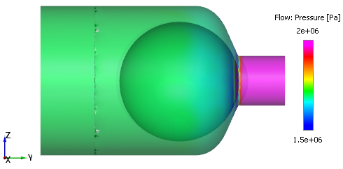
Pressure contours on the Volume
To obtain the pressure contours on the volumes:
- Select Boundaries in the Geometric Entities Panel by using the Group Entities by Volumes/Types
 icon in the Geometric Entities Panel.
 - Select Pressure from the Variables list under Variable drop-down list in the Results Panel. For variables and legends, refer Post-Processing.
- Specify Min as 1.5e+06 Pa and Max as 2e+06 Pa in the Results Panel.
- Select Transparent for Transparency in the View Tab of Properties Panel.
Creating a section
The contours on the valve are viewed on a section on the XY- plane.
- Click Create a Cross-Section
 icon in the Geometric Entities Panel. A new entities Section 01 is created under Derived Surfaces.
 - Select Section 01 under Derived Surfaces and specify the Type as Plane X and Position as 0 m in the Geometry Tab of Properties Panel.
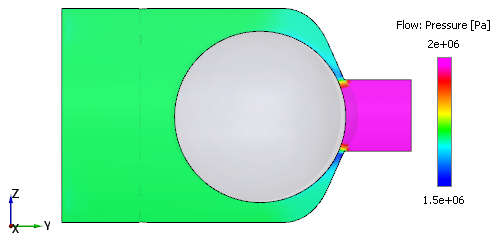
Pressure contours
- Select Section 01 under Derived Surfaces in the Geometric Entities Panel.
- Select Pressure from the Variables list under Variable drop-down list in the Results Panel.
- Specify Min as 1.5e+06 Pa and Max as 2e+06 Pa in the Results Panel.
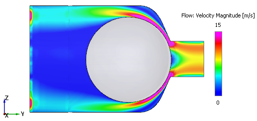
Velocity contours
To obtain the velocity magnitude contours on the section.
- Select the Section 01 under Derived Surfaces in the Geometric Entities Panel.
- Select Velocity Magnitude from the Derived Variables list under Variable drop-down list in the Results Panel.
- Specify Min as 0 m/s and Max as 15 m/s in the Results Panel.
Changes to the display, such as legend, contour color, image sizing and transparency can be made under the View Tab of Properties Panel.