Building the Mesh
This section describes the step-by-step procedure for preparing the mesh for the ball 3D valve simulation. The Valve Template Mesher is used to create the ball 3D valve mesh and the General Mesher is used to create the mesh for the inlet and outlet.
Ball 3D Valve
- Select Valve Template Mesher in the Mesh Panel.
- Select Ball 3D Valve from Valve Type drop-down list in the Properties Panel.
- Select CAD Surfaces ballCAD in the Geometric Entities Panel and click Add Surfaces
 icon for Ball CAD in the Properties Panel. icon for Ball CAD in the Properties Panel.
- Select CAD Surfaces outerCAD in the Geometric Entities Panel and click Add Surfaces icon for Outer CAD in the Properties Panel.
- Enter the parameters as follows.
- Click Build ball3D Mesh. A new mesh ball3d_valve is created under Built Meshes in the Geometric Entities Panel.
- The meshed volume ball3d_valve is generated under Volumes.
|
|
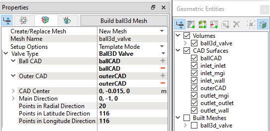
Figure 6.640 - Ball 3D valve mesh settings
|
Inlet
- Select General Mesher in the Mesh Panel.
- Select Advanced Mode for the Setup Options drop-down list.
- Select CAD Surfaces inlet_inlet, inlet_mgi and inlet_wall in the Geometric Entities Panel.
- Click Add Surfaces icon for CAD Surfaces in the Properties Panel.
- Enter Maximum Cell Size as 0.01, General.Minimum Cell Sizes as 0.0002 and Cell Size on Surfaces as 0.005 in the Properties Panel.
- Select Yes from Refine Cells next to Boundary Cells drop-down list.
- To refine the interface, select inlet_mgi from CAD Surfaces, User Input from Cell Size on Boundaries drop-down list and enter 0.0025 for Size in the Properties Panel.
- Select Refine One Level from Min. Cell Refinement on Boundaries drop-down list.
- Click Create Mesh. A new mesh inlet is created under Built Meshes in the Geometric Entities Panel.
- The meshed volumes inlet is generated under Volumes.
|
|
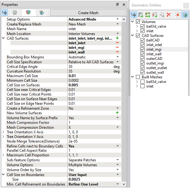
Figure 6.641 - Inlet mesh settings
|
Outlet
- Select General Mesher in the Mesh Panel.
- Select CAD Surfaces outlet_outlet, outlet_mgi and outlet_wall in the Geometric Entities Panel and click Add Surfaces icon for CAD Surfaces in the Properties Panel.
- Enter Maximum Cell Size as 0.02, General.Minimum Cell Sizes as 0.0004 and Cell Size on Surfaces as 0.01 in the Properties Panel.
- To refine the interface, select outlet_mgi from CAD Surfaces and User Input from Cell Size on Boundaries drop-down list, enter 0.01 for Size in the Properties Panel.
- Click Create Mesh. A new mesh outlet is created under Built Meshes in the Geometric Entities Panel.
- The meshed volumes outlet is generated under Volumes.
|
|
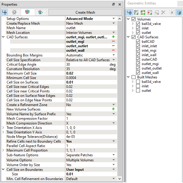
Figure 6.642 - Outlet mesh settings
|
The mesh created for the fluid domain is shown below:
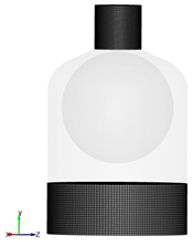
Figure 6.643 - Inlet and Outlet mesh
|
|
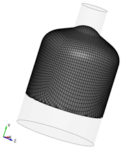
Figure 6.644 - Ball valve chamber mesh
|
|
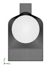
Figure 6.645 - Cross section showing ball valve mesh
|
Create interfaces
In this section, the Mismatched Grid Interfaces (MGIs) are generated between boundaries.
The steps to create the MGIs are shown below:
- In Geometric Entities Panel > Volumes > Boundaries, select Boundaries as shown in Table 6.36.
- Click Connect Selected Boundaries via MGI
 icon to create the MGI entities.
A group display of entities can be viewed using the Group Entities by Volumes/Types  icon at Geometric Entities Panel toolbar.
| Inlet and Ball valve chamber |
inlet_mgi and ball3d_valve_outer |
MGI01 |
| Ball valve chamber and outlet |
ball3d_valve_outer and outlet_mgi |
MGI02 |
Table 6.36 - Creating interfaces
The new entities are created under MGI in Volumes. The interface between the boundaries are improved by changing the projection tolerance. The steps to change the MGI tolerance is as follows:
- Select Mismatched Grid Interfaces MGI01 in the Geometric Entities Panel and enter the following parameters in the Properties Panel.
- Projection Method: Planar
- Position: 0,-0.0095,0
- Boundary Normal: 0,1,0
- Projection Tolerance: 0.01
- Normal Tolerance: 60
- Face Normal Tolerance: 60
- Face Distance Tolerance: 0.05
Select Mismatched Grid Interfaces MGI02 in the Geometric Entities Panel and enter the following parameters in the Properties Panel.
- Projection Method: Planar
- Position: 0,-0.0215,0
- Boundary Normal: 0,1,0
- Projection Tolerance: 0.01
- Normal Tolerance: 60
- Face Normal Tolerance: 60
- Face Distance Tolerance: 0.05
The interfaces MGI01_ball3d_valve_outer_inlet_mgi and MGI02_ball3d_valve_outer_outet_mgi are generated are under Interfaces, refer Figure 6.648.
|
|
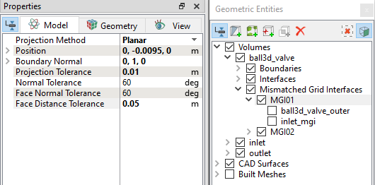
Figure 6.646 - MGI01 projection settings
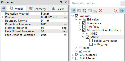
Figure 6.647 - MGI02 projection settings
|
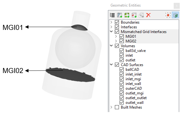
Figure 6.648 - Created interfaces
| ´ |
Note: If MGIs are created by connecting the wrong boundaries, delete the created MGIs by clicking on Delete Selected Geometric Entity icon and then recreate the MGIs icon and then recreate the MGIs |