|
You are here: Fluid Machinery Templates and Tutorials > Ball Valve > Ball 3D Valve Tutorial > Defining Physics and Conditions
|
Defining Physics and Conditions
The physics and conditions are specified as follows.
Adding Modules
|
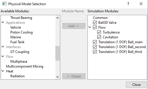
Figure 6.649 - Adding modules |
Ball 3D Operating Parameters
|
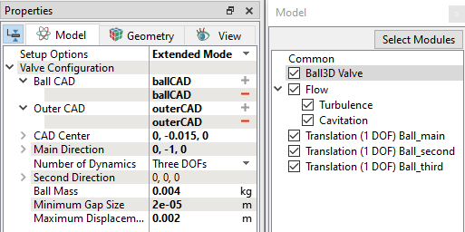
Figure 6.650 - Ball3d operating parameters |
Flow Parameters
|
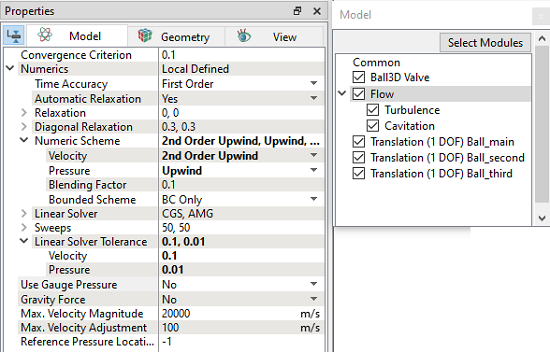
Figure 6.651 - Flow parameters |
| ´ | Note: The Number of Time Steps per Cycle is an important parameter and must be large enough to achieve a smooth solution. |
Translation (1 DOF) Ball_second Operating Parameters
|
Figure 6.653 - Translation (1 DOF) Ball_second operating parameters |
|
Note: An initial displacement of 0.0001 m is provided in the second direction for demonstration of 3D movement of the ball valve. |
Translation (1 DOF) Ball_third Operating Parameters
|
Figure 6.654 - Translation (1 DOF) Ball_third operating parameters |
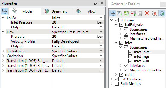
Boundary Conditions
The boundary conditions for the Ball 3D valve are specified as follows:
- Select Boundaries from the Geometric Entities Panel.
- In the Model Tab of Properties Panel, verify the boundary type for the ball3d drop-down list as Ball Wall for ball3d_valve_inner boundary.
|
Note: The boundary conditions for the ball 3D valve volume generated using the Ball Valve Template Mesher are automatically set by the template. |
Inlet
|
Outlet
|
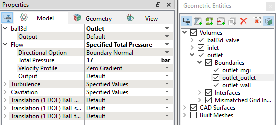
Figure 6.656 - Outlet conditions |
Fluid Properties
Enter the parameters for Operating Conditions as follows, except for Inlet volume.
Select Inlet volume in the Geometric Entities Panel, enter the parameters for Operating Conditions as follows:
|
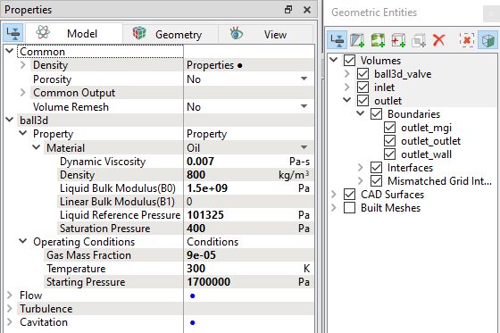
Figure 6.657 - Fluid properties |