中文 English

Building the Mesh

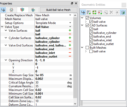
This section describes the step-by-step procedure for preparing the mesh for the ball valve simulation. The Valve Template Mesher is used to create the valve mesh.

Valve
  1. Select Valve Template Mesher in the Mesh Panel.
  2. Select Ball Valve from Valve Type drop-down list in the Properties Panel.
  3. Select CAD Surfaces ball in the Geometric Entities Panel and click Add Surfaces icon for Valve Surfaces in the Properties Panel.
  4. Select CAD Surfaces ballvalve_cylinder and click Add Surfaces icon for Cylinder Surfaces in the Properties Panel.
  5. Select CAD Surfaces ballvalve_end, ballvalve_inlet and ballvalve_outlet. Click Add Surfaces icon for Valve End Surfaces in the Properties Panel.
  6. Enter the parameters as follows.
    • Opening Direction: 0,-1,0
    • Minimum Gap Size: 5e-05 m
    • Maximum Displacement: 0.002 m

    • Maximum Cell Size: 0.02
    • Minimum Cell Size: 0.001
    • Cell Size on Surfaces: 0.02
  7. Click Build Ball Valve Mesh. A new mesh ball valve is created under Built Meshes in the Geometric Entities Panel.
  8. The meshed volume ball valve is generated under Volumes.
 

Figure 6.611 - Ball valve mesh settings


The mesh created for the fluid domain is shown below.

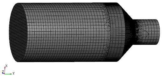
Figure 6.612 - Ball valve volume mesh


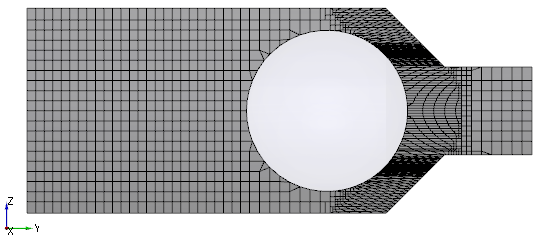
Figure 6.613 - Ball valve section mesh


Copyright © 2023 Simerics Inc.,