Defining Physics and Conditions
The physics and conditions are specified as follows.
Adding Modules
- Ball Valve is automatically added to the Model Panel, when the Ball valve template is used to generate the mesh.
- Click Select Modules in the Model Panel. The Physical Model Selection dialog box opens.
- Select Turbulence, Cavitation and Translation (1 DOF) under Available Modules and click Add.
-
Click Close to close the Physical Model Selection dialog box.
|
|
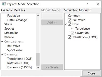
Figure 6.614 - Adding modules
|
Ball Valve Operating Parameters
- Select Ball Valve in the Model Panel.
- Select Translation (1 DOF) from the Dynamics drop-down list in the Model Tab of Properties Panel, to link the motion of the Ball Valve to the Translation (1 DOF) module.
- Set Minimum Gap Size as 5e-05 m and Maximum Displacement as 0.002 m.
- Select Automatic in the Closure Model drop-down list.
|
|
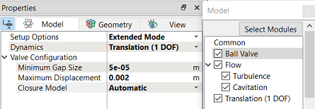
Figure 6.615 - Ball valve-Operating parameters
|
| |
Note:Closure Model determines whether the flow is fully blocked at the Minimum Gap Size.
|
Translation (1 DOF) Operating Parameters
- Select Translation (1 DOF) in the Model Panel.
-
Enter the Time Definition parameters in the Model Tab of Properties Panel.
- Select Force Balance in the Motion Type drop-down list.
-
Enter the parameters for Motion Type as follows.
- Enter Movement Direction as 0,-1,0.
| ´ |
Note: The Number of Time Steps per Cycle is an important parameter and needs to be large enough to achieve a smooth solution. |
|
|
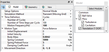
Figure 6.616 - Translation (1 DOF) - Operating parameters
|
Boundary Conditions
The boundary conditions for the Valve are preset by the Valve Template Mesher and are specified as follows:
- Select the entities under Boundaries in the Geometric Entities Panel, as shown in Table 6.34.
- In the Model Tab of Properties Panel, verify the boundary type in the Ball Valve drop-down list, as shown in Table 6.34.
| ball
|
Valve
|
| ballvalve_cylinder
|
Cylinder
|
| ballvalve_end
|
Valve End
|
Table 6.34 - Valve Boundary type
Inlet
- Select ballvalve_inlet from the Boundaries list in the Geometric Entities Panel.
- Select Inlet from Ball Valve drop-down list in the Model Tab of Properties Panel.
- Click Edit Expression
 icon in Inlet Pressure to open the Expression Editor dialog box . icon in Inlet Pressure to open the Expression Editor dialog box .
-
Copy and paste the expressions written under Description drop-down list for Global Expressions, see Figure 6.617
 Description Description
fre = 100 # Hz
P0 = 3E5 # Pa
dp = 2E5 # Pa
inlet_p = P0 + dp*sin(2*pi*fre*time) # Pa
- Click OK and enter inlet_p for the
Inlet Pressure in the Model Tab of Properties Panel.
|
|
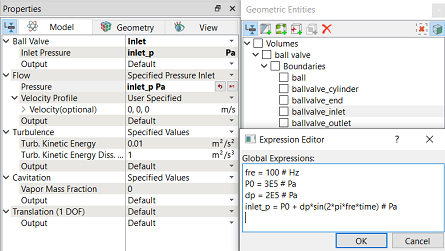
Figure 6.617 - Inlet conditions
|
Outlet
-
Select ballvalve_outlet from the Boundaries list in the Geometric Entities Panel.
- Select Outlet from the Ball Valve drop-down list in the Model Tab of Properties Panel.
- Enter Outlet Pressure as 101325 Pa.
|
|
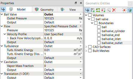
Figure 6.618 - Outlet conditions
|
Fluid Properties
- Select Volumes in the Geometric Entities Panel.
- Select Model Tab in the Properties Panel.
- Enter the parameters in Property list as follows.
- Material: Oil
- Dynamic Viscosity: 0.007 Pa-s
- Density: 800 kg/m3
-
Liquid Bulk Modulus (B0): 1.5e+09 Pa
-
Liquid Reference Pressure: 101325 Pa
-
Saturation Pressure: 400 Pa
Enter the parameters for Operating Conditions as follows.
- Gas Mass Fraction: 9e-05
- Operating Temperature: 300 K
- Starting Pressure: 101325 Pa
|
|
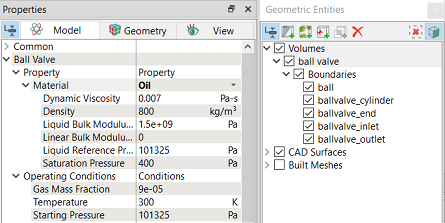
Figure 6.619 - Fluid properties
|