6.11.1 Geometry and Domain
The simulation of the ball valve requires understanding of the geometry and the fluid domain enclosed by the surfaces of the valve. The general fluid volume of the ball valve and prerequisite steps, before taking into Simerics-MP+ is described as follows:
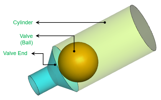
Figure 6.596 - Parts of the deforming volume of a Ball valve-Valve, Cylinder and Valve End Surfaces
Prerequisite steps
- The fluid volumes for the ball valve consist of Inlet, Outlet ports and deforming volume.
- For a valve, the fluid volume must be further split into potential expansion/compression zones. For deforming volume, template requires valve, valve end, and cylinder (guiding surface). The guiding surfaces in a ball valve template should be of cylindrical shape as shown in Figure 6.597.
- While extracting the fluid volume, ensure the position of the valve is between the valve end surfaces.
- It is preferred that the initial position of the valve must be half way between two valve ends or half way through the maximum possible displacement for more uniform mesh generation.
Fluid Domain
The fluid volume in a ball valve is defined by CAD Surfaces which enclose them. The ball valve template primarily consists of the following parts/volumes: Inlet, Valve, Outlet, Cylinder and Valve End as shown in Figure 6.597.
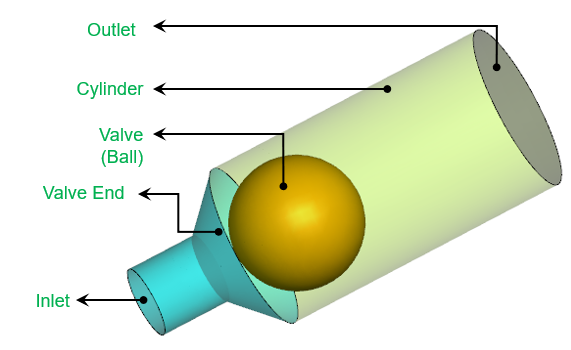
Inlet: The fluid enters the domain through the inlet boundary. Pressure boundary condition is generally specified at the inlet.
Valve: The fluid volume which deforms based on the ball motion.
Outlet: The fluid exits the domain through the outlet boundary. Pressure boundary condition is generally specified at the outlet.
For an example of the Ball Valve simulation, refer Ball Valve Tutorial.