|
You are here: Fluid Machinery Templates and Tutorials > Bent Axis Piston Pump > Bent Axis Piston Pump Tutorial > Computational domain
|
Computational domain
This section explains the preparation of surfaces to create the domain.
The pre-requirement in a bent axis piston pump simulation is the preparation of CAD Surfaces, for a virtual neutral position of the pump in which the cylinder remains in the “neutral” position. If a neutral geometry is not available, this must be done in CAD by rotating the ports, valve plate, and a single cylinder around the joint of the bent axis (Bent Center) until the Cylinder Block Axis Vector aligns with the Flange Axis Vector, and then adjusting the piston position (and volume of the cylinder) by rotating around the center of the ball joint (as determined in PumpLinx by the Flange Center and Flange Center to Ball Joint Radius) until it fits within the cylinder.
This tutorial is performed with a neutral geometry, in which the cylinders are rotated to incorporate the bend of the axis. The surfaces are then split, combined and renamed to prepare the computational domain.
Pump Surfaces
- Select Split/Combine Geometry or Grid in the Mesh Panel.
- Select CAD Surfaces pump in the Geometric Entities Panel.
- Select Split Disconnected from the Operation drop-down list in the Properties Panel, click Split Disconnected. Eight new CAD Surfaces are created in the Geometric Entities Panel.
- Rename CAD Surfaces pump_01, pump_02 and pump_03 as inlet, outlet and piston respectively.
-
Select the remaining CAD Surfaces and select Combine from the Operation drop-down list in the Properties Panel, click Combine
-
Rename the combined CAD Surfaces as vp.
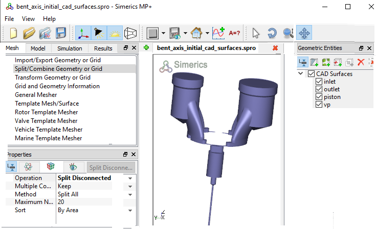
Figure 6.480 - Split of CAD surfaces
Inlet Surfaces
|
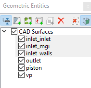
Figure 6.481 - Inlet surfaces |
Outlet Surfaces
|

Figure 6.482 - Outlet surfaces |
Piston Surfaces
|
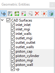
Figure 6.483 - Piston surfaces |
Valve Plate Surfaces
|
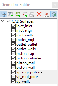
Figure 6.484 - Valve plate surfaces |
| CAD Surfaces | Rename as |
|---|---|
| vp, vp_01, vp_02, vp_03, vp_04, vp_05, vp_16 | vp_walls |
| vp_06,vp_07, vp_10, vp_11, vp_12 | vp_mgi_pistons |
| vp_08, vp_09, vp_13, vp_14, vp_15 | vp_mgi_ports |
Table 6.22 - Combine CAD surfaces
| ´ | Note: Splitting of the surfaces can also be done by mouse selection using the Split by Mouse option from the Method drop-down list in the Geometry Tab of Properties Panel. |