Building the Mesh
This section describes the step-by-step procedure for preparing the mesh for the bent axis piston pump. The Rotor Template Mesher is used to create the piston-cylinder assembly mesh and the General Mesher is used to create the mesh for the inlet, outlet and the valve plate.
Inlet and Outlet Meshes
- Select General Mesher in the Mesh Panel.
- Select CAD Surfaces inlet_inlet, inlet_mgi, inlet_walls, outlet_mgi, outlet_outlet, outlet_walls in the Geometric Entities Panel and click Add Surfaces
 icon for CAD Surfaces in the Properties Panel. icon for CAD Surfaces in the Properties Panel.
- Enter Maximum Cell Size as 0.01, Minimum Cell Size as 0.001 and Cell Size on Surfaces as 0.005 in the Properties Panel.
- Click Create Mesh. A new mesh mesh is created under Built Meshes in the Geometric Entities Panel.
- The meshed volumes inlet and outlet are generated under Volumes.
|
|
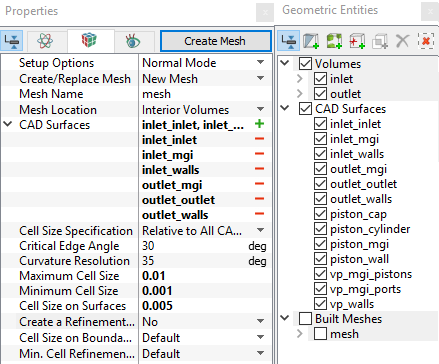
Figure 6.485 - Inlet and Outlet mesh settings
|
Valve plate Mesh
- Select General Mesher in the Mesh Panel.
- Select CAD Surfaces vp_mgi_pistons, vp_mgi_ports and vp_walls in the Geometric Entities Panel and click Add Surfaces icon for CAD Surfaces in the Properties Panel.
- Enter the Maximum Cell Size as 0.005, Minimum Cell Size as 0.001 and Cell Size on Surfaces as 0.0025 in the Properties Panel.
- Click Create Mesh. A new mesh vp is created under Built Meshes in the Geometric Entities Panel.
- The meshed volumes vp, vp_1, vp_2, vp_3 and vp_4 are generated under Volumes.
- Select Split/Combine Geometry or Grid in the Mesh Panel.
- Select the Volumes vp, vp_1, vp_2, vp_3 and vp_4.
- Select Combine from the Operation drop-down list in the Properties Panel, click Combine and rename as valve_plate.
- Select the Boundaries sequentially as shown in Table 6.23. Select Combine from the Operation drop-down list in the Properties Panel and click Combine.
|
|
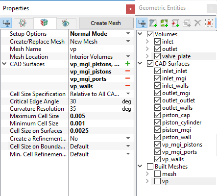
Figure 6.486 - Valve plate mesh settings
|
| vp_walls, vp_walls_1, vp_walls_2, vp_walls_3 and vp_walls_4 |
vp_walls |
| vp_mgi_pistons, vp_mgi_pistons_1, vp_mgi_pistons_2, vp_mgi_pistons_3, vp_mgi_pistons_4 |
vp_mgi_pistons |
| vp_mgi_ ports, vp_mgi_ ports_1, vp_mgi_ ports_2, vp_mgi_ ports_3, vp_mgi_ ports_4 |
vp_mgi_ ports |
Table 6.23 - Connect and rename boundaries
| ´ |
Note: Two connected volumes, such as the inlet and valve plate, or valve plate and outlet are not to be meshed together using the General Mesher, and will be connected later using Mismatched Grid Interfaces. |
Piston - cylinder assembly Mesh
- Select Rotor Template Mesher in the Mesh Panel.
- Select Bent Axis Piston for Rotor Type in the Properties Panel.
- Select CAD Surfaces piston_wall in the Geometric Entities Panel, click Add Surfaces icon for Piston Wall in the Properties Panel. Similarly select CAD Surface piston_cylinder, piston_cap and piston_mgi, click Add Surfaces icon for Cylinder Wall, Cylinder Cap and Cylinder MGI respectively.
-
Enter the parameters as follows.
- Number of Pistons: 9
- Flange Axis Vector: 0,0,1
-
Flange Center: 0,0,0
- Flange Center to Ball Joint Radius: 0.0417 m
- Maximum Cell Size: 0.01
- Minimum Cell Size: 0.001
- Cell Size on Surfaces: 0.005
- Click Build Bent Axis Piston Mesh. The new mesh bentaxis is created under Built Meshes in the Geometric Entities Panel.
- The meshed volume bentaxis is generated under Volumes and rename as piston.
|
|
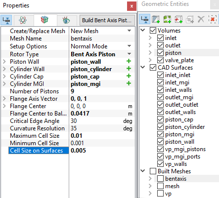
Figure 6.487 - Piston - cylinder mesh settings
|
| |
Note:
- The geometry contains only one piston. The mesh for all the pistons specified under Number of Pistons is automatically generated by the Rotor Template Mesher.
- The imported geometry does not include any leakage gap by default. The parameters for the gaps can be adjusted by selecting a Advanced Mode under Setup Options in the Properties Panel.
|
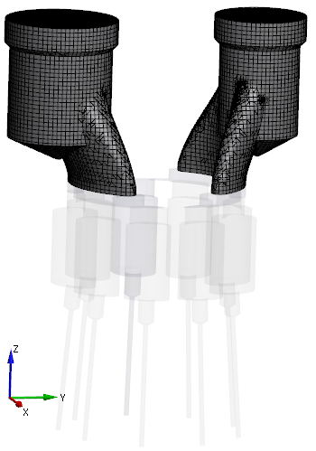
Figure 6.488 - Inlet and Outlet mesh
|
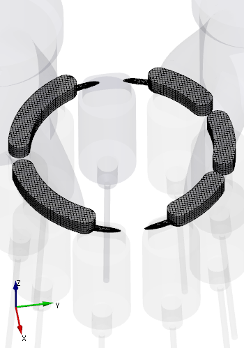
Figure 6.489 - Valve plate mesh
|
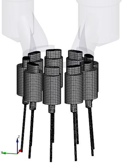
Figure 6.490 - Piston-cylinder assembly mesh
|
Create interfaces
In this section, the Mismatched Grid Interfaces (MGIs) are generated between boundaries.
The steps to create the MGIs shown below:
- Geometric Entities Panel > Volumes > Boundaries, select Boundaries as shown in Table 6.24.
-
Click Connect Selected Boundaries via MGI  icon to create the MGI entities refer, Figure 6.491.
A group display of entities can be viewed using the Group Entities by Volumes/Types  icon at Geometric Entities Paneltoolbar.
| Ports and valve plate |
inlet_mgi, outlet_mgi, and vp_mgi_ports |
MGI01 |
| Pistons and valve plate |
piston_mgi and vp_mgi_pistons |
MGI02 |
Table 6.24 - Creating interfaces
The new entities are created under MGI in Volumes refer, Figure 6.492.
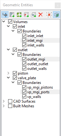
Figure 6.491 - Connecting Ports and Valve plate
|
|
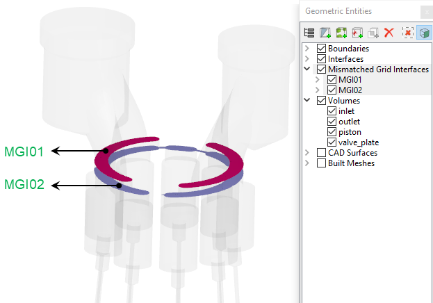
Figure 6.492 - Created interfaces
|
| |
Note: If MGIs are created by connecting the wrong boundaries, delete the created MGIs by clicking on Delete Selected Geometric Entity  icon and recreate the MGIs. icon and recreate the MGIs.
|