中文 English

Defining Physics and Conditions

The physics and conditions are specified as follows.

Adding Modules
  1. Click Select Modules in the Model Panel. The Physical Model Selection dialog box opens.
  2. Bent Axis Piston is automatically added to the Model Panel by the Rotor Template Mesher.
  3. Select Cavitation under Available Modules and click Add.
  4. Click Close to close the Physical Model Selection dialog box.


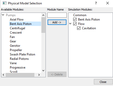
Figure 6.493 - Adding modules

General Operating Parameters
  1. Select Bent Axis Piston in the Model Panel.
  2. Enter Number of Revolutions as 3 and Time Steps Per Piston Rotation as 40 for Time Definition in the Model Tab of Properties Panel.
  3. Enter the parameters for Angular Velocity Definition as follows.

    • Cylinder Block Axis Vector: 1,0,1

    • Distance From Bent Center to Flange Center: 0.01
    • Rotational Direction: Clockwise

    • Rotational Speed: 1000 rpm


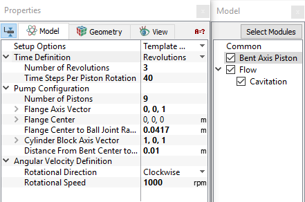
Figure 6.494 - Operating parameters

´

Note: 

  1. Some parameters such as Number of Pistons, Flange Axis Vector, Flange Center and Flange Center to Ball Joint Radius in the Bent Axis Piston module are automatically defined by the Rotor Template Mesher.
  2. The parameters Flange Center to Ball Joint Radius and Distance From Bent Center to Flange Center determine the position and motion of the pistons as the pump rotates during simulation.
  3. The Number of Pistons is used for calculating the time-step. The Number Steps Per Piston Rotation determines the angle of rotation each time-step.


Boundary Conditions

The boundary conditions are specified as follows:

Inlet
  1. Select inlet_inlet from the Boundaries list under Volumes in the Geometric Entities Panel.
  2. Select Inlet from the Bent Axis Piston drop-down list in the Model Tab of Properties Panel.
  3. Enter Inlet Pressure as 200000 Pa.
 

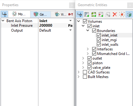
Figure 6.495 - Inlet conditions


Outlet
  1. Select  outlet_outlet from the Boundaries list under Volumes in the Geometric Entities Panel.

  2. Select Outlet from the Bent Axis Piston drop-down list in the Model Tab of Properties Panel.
  3. Enter Outlet Pressure as 1e+07 Pa.


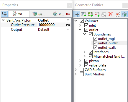
Figure 6.496 - Outlet conditions

Fluid Properties
  1. Select Volumes in the Geometric Entities Panel.
  2. Select Model Tab in the Properties Panel.
  3. Enter the parameters for the Property list as follows.
  • Material: Oil
  • Dynamic Viscosity: 0.007 Pa-s
  • Density: 800 kg/m3
  • Liquid Bulk Modulus(B0): 1.5e+09 Pa
  • Liquid Reference Pressure101325 Pa
  • Saturation Pressure: 400 Pa
  • In the expanded list of Operating Conditions define the attributes as follows.

    • Gas Mass Fraction: 9e-05
    • Operating Temperature: 300 K
  •  

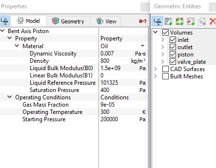
    Figure 6.497 - Fluid properties


    Copyright © 2023 Simerics Inc.,