6.8.1 Geometry and Domain
The simulation of the bent axis piston pump requires understanding of the geometry and the fluid domain enclosed by the surfaces of the pump. The general fluid volume of the bent axis piston pump and prerequisite steps, before taking into Simerics-MP+ is described as follows:
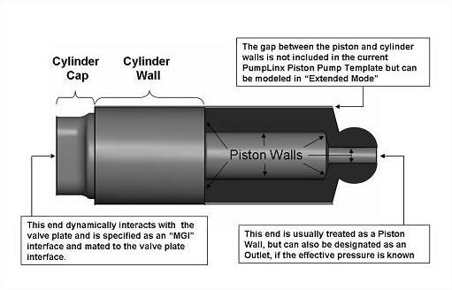
Figure 6.451 - Bent axis piston
Prerequisite steps
- The fluid volumes for the bent axis piston pump consist of inlet, outlet ports, valve plate and reference piston assembly.
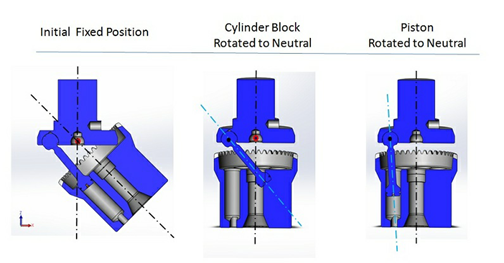
- For pumping chamber, the template requires reference piston assembly surfaces to be imported. The reference piston needs to be in neutral position while using the template mesh. If a neutral geometry is not available, this must be done in CAD by rotating the ports, valve plate, and a single cylinder around the joint of the bent axis (bent center) until the cylinder block axis vector aligns with the flange axis vector, and then adjusting the piston position (and volume of the cylinder) by rotating around the center of the ball joint (as determined in Simerics-MP+ by the flange center and flange center to ball joint radius) until it fits within the cylinder as shown in the Figure 6.452..
- The template creates the leakage gaps based on the values provided. Hence, the fluid volumes should be imported without clearances.
- The piston face may need to be squared off where it contacts the cylinder walls, i.e. any bevel or curvature may need to be simplified. Note that this does not preclude inclusion of flow paths in the center of the piston.
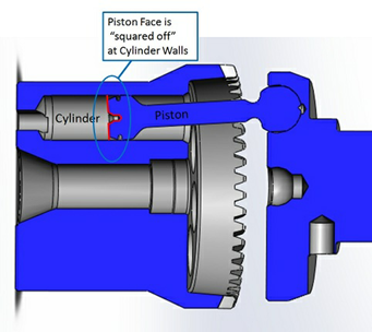
Figure 6.453 - Bent axis piston face |
Fluid Domain
The fluid volume in a bent axis piston pump is defined by CAD Surfaces which enclose them. This pump model primarily consists of the following volumes: Inlet, Outlet, Valve plate and Piston cylinder (adjacent to the outlet port), as shown in Figure 6.454.
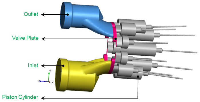
Inlet: The fluid enters the pump through the inlet boundary. Pressure is generally specified as a boundary condition at the inlet, while the other surfaces of the inlet volume are treated as walls.
Valve Plate: The fluid volume enclosed between inlet/outlet ports and cylinder.
Piston Cylinder: This is the pumping chamber, where fluid gets sucked and compressed.
Outlet: The fluid exits the pump at the outlet boundary. Pressure is generally specified as a boundary condition at the outlet, while the other surfaces of the outlet volume are treated as walls.
For an example of the bent axis piston pump simulation, refer Bent Axis Piston Tutorial.