|
You are here: Fluid Machinery Templates and Tutorials > Centrifugal Pump > Centrifugal Pump Tutorials > Building the Mesh
|
Building the Mesh
This section describes the step-by-step procedure for preparing the mesh for the centrifugal pump. The mesh is created using the General Mesher.
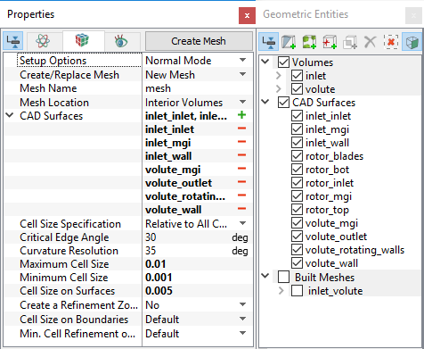
Rotor Chamber Mesh
|
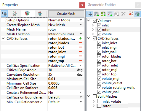
Figure 6.17 - Rotor mesh settings |
| Note: The mesh can be edited/ replaced by selecting it under Built Meshes, and modify the mesh parameters in the Properties Panel. Click Create Mesh to reflect the changes. |
The mesh created for the fluid domain is shown below:
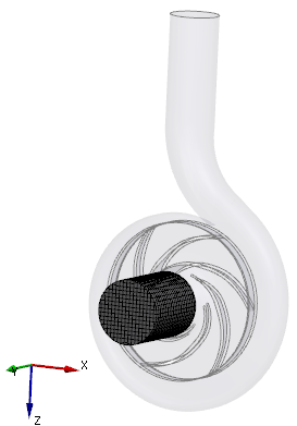
Figure 6.18 - Inlet mesh |
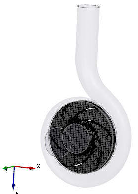
Figure 6.19 - Rotor mesh |
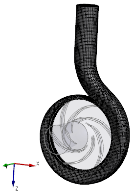
Figure 6.20 - Volute mesh |
Create interfaces
In this section, the Mismatched Grid Interfaces (MGIs) are generated between boundaries.
The steps to create the MGIs are as follows:
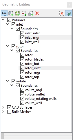
- Geometric Entities Panel > Volumes > Boundaries, select boundaries as shown in Table 6.1.
- Click Connect Selected Boundaries via MGI
 icon to create the MGI entities (see, Figure 6.21)
A group display of entities can be viewed using the Group Entities by Volumes/Types ![]() icon in Geometric Entities Panel toolbar.
icon in Geometric Entities Panel toolbar.
| Connecting interfaces | Boundaries | Entity |
|---|---|---|
| Inlet and rotor chamber | inlet_mgi and rotor_inlet | MGI01 |
| Rotor chamber and volute | rotor_mgi and volute_mgi | MGI02 |
Table 6.1 - Creating interfaces
The new entities are created under MGI in Volumes (see, Figure 6.22).
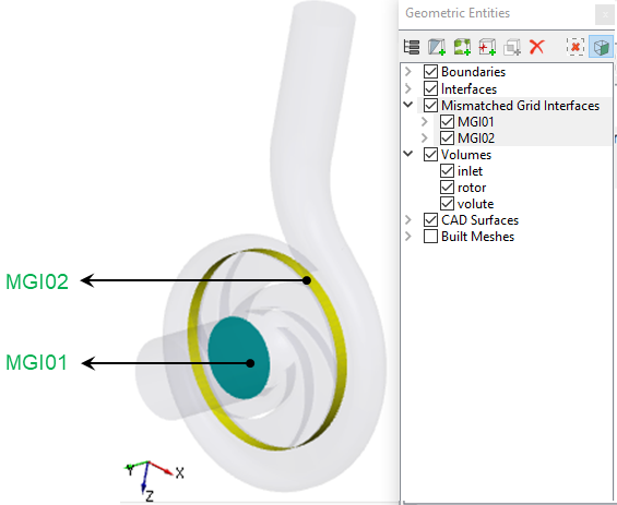
| ´ | Note: If MGIs are created by connecting the wrong boundaries, delete the created MGIs by clicking on Delete Selected Geometric Entity |