中文 English
You are here: Fluid Machinery Templates and Tutorials > Centrifugal Pump > Centrifugal Pump Tutorials > Defining Physics and Conditions

Defining Physics and Conditions

The physics and conditions are specified as follows:

Adding Modules
  1. Click Select Modules in the Model Panel. The Physical Model Selection dialog box opens.
  2. Select Centrifugal under Available Modules list, click Add.
  3. Select Turbulence under Available Modules list and click Add.
  4. Select Cavitation under Available Modules list and click Add.
  5. Click Close to close the Physical Model Selection dialog box.
 

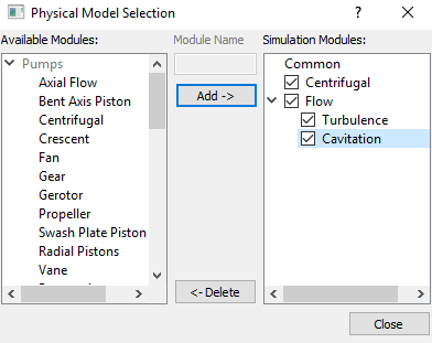
Figure 6.23 - Adding modules

General Operating Parameters
  1. Select Centrifugal in the Model Panel.
  2. Enter Number of Blades as 6 for Pump Configuration list in the Properties Panel.
  3. Enter the parameters for Angular Velocity Definition as follows.

    • Rotational Direction: Counterclockwise
    • Rotational Speed: 2950 rpm
    • Rotational Axis Vector: 0, 1, 0
  4. Ensure the parameter Rotor Center as 0,0,0.
 

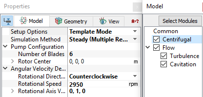
Figure 6.24 - Operating parameters

Boundary Conditions

The boundary conditions are specified as follows:

Inlet
  1. Select inlet_inlet from the Boundaries list under Volumes in the Geometric Entities Panel.
  2. Select Inlet from the Centrifugal drop-down list in the Model Tab of Properties Panel.
  3. Enter Total Pressure as 101325 Pa.


Figure 6.25 - Inlet conditions

Rotor
  1. Select rotor_blades, rotor_bot and rotor_top from the Boundaries list in the Geometric Entities Panel.

  2. Select Rotor from the Centrifugal drop-down list in the Model Tab of Properties Panel.
´ Note:  The rotational parameters specified for Rotor boundary are same as the values defined under Centrifugal in the Model Panel. These values can not be changed as indicated by blue font.
 

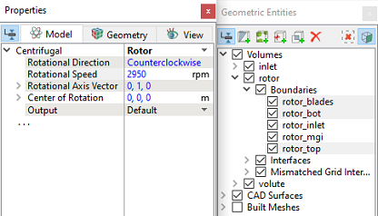
Figure 6.26 - Rotor conditions

Rotating wall in the volute
  1. Select  volute_rotating_walls from the Boundaries list in the Geometric Entities Panel.
  2. Select Rotating Wall from the Centrifugal drop-down list in the Model Tab of Properties Panel.
 

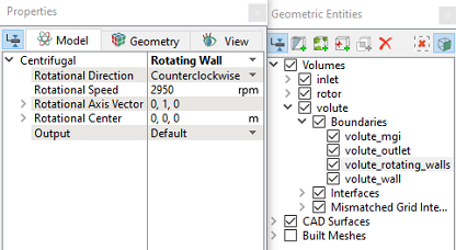
Figure 6.27 - Volute Rotating Wall conditions
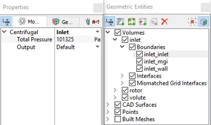
Outlet
  1. Select  volute_outlet from the Boundaries list in the Geometric Entities Panel.

  2. Select Outlet from the Centrifugal drop-down list in the Model Tab of Properties Panel.
  3. Enter 0.028 m3/s for Volumetric Flux.
 

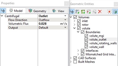
Figure 6.28 - Outlet conditions

Fluid Properties
  1. Select Volumes in the Geometric Entities Panel.
  2. Select Model Tab in the Properties Panel.
  3. Enter the parameters for Property list as follows.
  • Material : Water
  • Dynamic Viscosity: 0.001003 Pa-s
  • Density: 998 kg/m3
  • Liquid Bulk Modulus(B0): 2.15e+09 Pa
  • Liquid Reference Pressure: 101325 Pa
  • Saturation Pressure: 3610 Pa
  • Enter the parameters for Operating Conditions as follows.

    • Gas Mass Fraction: 2.3e-05
    • Operating Temperature: 300 K
    • Starting Pressure: 101325 Pa
  •  

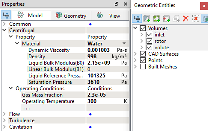
    Figure 6.29 - Fluid properties


    Copyright © 2023 Simerics Inc.,