Computational domain
This section define the steps involved in the preparation of surfaces to create the domain. This is done with the operations splitting, combining and renaming of the surfaces.
Pump Surfaces
- Select Split/Combine Geometry or Grid in the Mesh Panel.
- Select CAD Surface pump in the Geometric Entities Panel.
- Select Split Disconnected from the Operation drop-down list in the Properties Panel, click Split Disconnected.
-
Rename the three new CAD Surfaces entities pump_01, pump_02, and pump_03 as volute, rotor and inlet respectively in the Geometric Entities Panel.
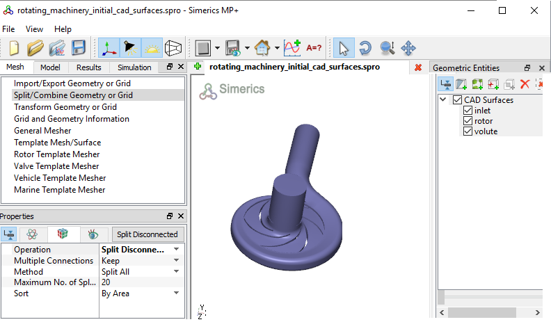
Figure 11.332 - Split of CAD surfaces
Inlet Surfaces
- Select CAD Surfaces inlet in the Geometric Entities Panel.
- Select Split by Angle from the Operation drop-down list in the Properties Panel.
- Enter 75 deg for Angle, click Split by Angle.Three new CAD Surfaces entities are created.
- Rename CAD Surfaces inlet_01, inlet_02,and inlet_03 as a inlet_wall, inlet_mgi and inlet_inlet respectively in the Geometric Entities Panel.
|
|
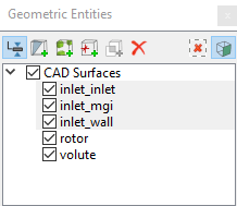
Figure 11.333 - Inlet surfaces
|
Rotor Surfaces
- Select CAD Surfaces rotor in the Geometric Entities Panel.
- Select Split by Angle from the Operation drop-down list in the Properties Panel.
- Enter 30 deg for Angle, click Split by Angle. Twenty new CAD Surfaces rotor_01 to rotor_20 are created in the Geometric Entities Panel.
- Rename CAD Surfaces rotor_01, rotor_02, rotor_03 and rotor_10 as rotor_top, rotor_bot, rotor_mgi and rotor_inlet respectively.
- Select the remaining CAD Surfaces and select Combine from the Operation drop-down list in the Properties Panel, click Combine.
- Rename the combined CAD Surfaces as rotor_blades.
|
|
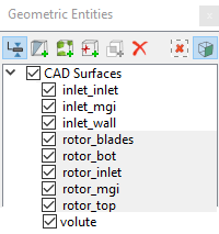
Figure 11.334 - Rotor surfaces
|
Volute Surfaces
- Select CAD Surfaces volute in the Geometric Entities Panel.
- Select Split by Angle from the Operation drop-down list in the Properties Panel.
- Enter 85 deg for Angle, click Split by Angle. Seven new CAD Surfaces volute_1 to volute_7 are created in the Geometric Entities Panel.
- Rename CAD Surfaces volute_1, volute_2 and volute_5 as a volute_wall, volute_mgi and volute_outlet respectively.
- Select the remaining CAD Surfaces and select Combine from the Operation drop-down list in the Properties Panel, click Combine.
- Rename the combined CAD Surfaces as volute_rotating_walls.
|
|
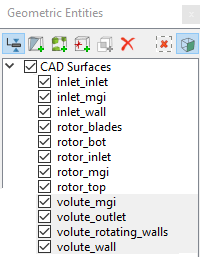
Figure 11.335 - Volute surfaces
|
| ´ |
Note: Splitting of the surfaces can also be done by mouse selection using the Split by Mouse option from the Method drop-down list in the Geometry Tab of Properties Panel. |