Defining Physics and Conditions
The physics and conditions are specified as follows.
Adding Modules
- Click Select Modules in the Model Panel. The Physical Model Selection dialog box opens.
- Select Cavitation and Turbulence modules, click Add.
-
Click Close, to close the Physical Model Selection dialog box.
|
|
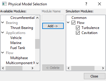
Figure 11.343 - Adding modules
|
Boundary Conditions
The boundary conditions are specified as follows.
Inlet
- Select inlet_inlet from the Boundaries list under Volumes in the Geometric Entities Panel.
- Select Specified Total Pressure from the Flow drop-down list in the Model Tab of Properties Panel and enter the following:
- Total Pressure: 101325 Pa
Select User Select from the Output drop-down list under Flow and set Volumetric Flow Rate and Average Total Pressure as Yes.
|
|
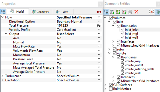
Figure 11.344 - Inlet conditions
|
Outlet
- Select volute_outlet from the Boundaries list under Volumes in the Geometric Entities Panel.
- Select Specified Volumetric Flux from the Flow drop-down list in the in the Model Tab of Properties Panel and enter the following:
- Flow Direction: Outflow
- Value: 0.028 m3/s
Select User Select from the Output drop-down list under Flow and set Volumetric Flow Rate and Average Total Pressure as Yes.
|
|

Figure 11.345 - Outlet conditions
|
Rotating Wall
-
Select rotor_blades, rotor_bot, rotor_top and volute_rotating_walls from the Boundaries list under Volumes in the Geometric Entities Panel.
- Select Rotating Wall from the Flow drop-down list in the Model Tab of Properties Panel and enter the following:
Select User Select from the Output drop-down list under Flow and set Power to Yes.
|
|
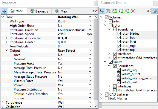
Figure 11.346 - Rotating Wall conditions
|
Rotor Volume Conditions
In Steady State Simulation, Non-inertial frame of approach is used to model impeller rotation.
Enter the parameters as follows:
- Select rotor from Volumes in the Geometric Entities Panel.
- Select Noninertial Frame from the Noninertial Frame drop-down list under Flow in the Properties Panel.
-
Enter the following under Noninertial Frame.
-
Rotational Direction: Counterclockwise
- Rotational Speed: 2950 rpm
- Rotational Center: 0,0,0 m
-
Rotational Axis Vector: 0, 1, 0
|
|
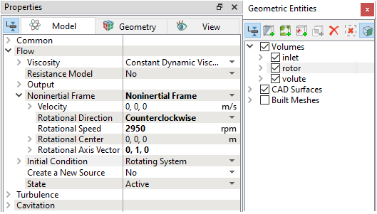
Figure 11.347 - Rotor Volume conditions
|
Fluid Properties
- Select Volumes in the Geometric Entities Panel.
- Select Model Tab in the Properties Panel.
- Enter the Liquid Density as 998 kg/m3 for the Density in the Model Tab of Properties Panel.
- Enter the Value as 0.001003 Pa-s for the Flow.
|
|
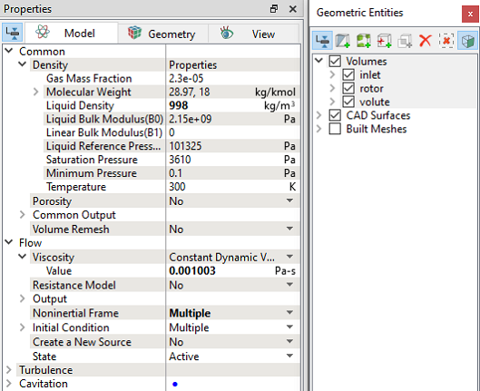
Figure 11.348 - Fluid properties
|