6.13.1 Geometry and Domain
The simulation of the Ball/Spool valve requires the understanding of the geometry and the fluid domain enclosed by the surfaces of the valve. The general fluid volume of the Ball/Spool valve and prerequisite steps, before taking into Simerics-MP+ are described as follows:
Prerequisite steps
- The fluid volume for the Ball/Spool Valve consists of Inlet, Outlet Ports and Deforming Volume.
- For a valve, the fluid volume must be further split into potential expansion/compression zones. For deforming volume, template requires valve, valve end, and cylinder (Guiding Surface). Ensure that guiding surfaces should be cylindrical.
- While extracting the fluid volume, ensure the position of the valve is between the valve end surfaces.
Fluid Domain
The fluid volume in a spool valve is defined by CAD Surfaces which enclose them. The Ball/Spool valve model primarily consists of the following parts/volumes : Inlet, Valve and Outlet.
Inlet: The fluid enters the domain through the inlet boundary. A pressure boundary condition is generally specified at the inlet, while the other surfaces of the inlet volume are treated as walls.
Valve: The fluid volume which deforms based on the valve motion.
Outlet: The fluid exits the domain through the outlet boundary. A pressure boundary condition is generally specified at the outlet, while the other surfaces of the outlet volume are treated as walls.
This analytical 1D model of valve can be attached to any hydraulic system. There are two analytical models available to do the analysis of the system. They are Ball valve and Spool valve.
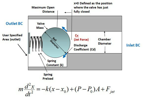
Figure 6.772 - Ball valve model |
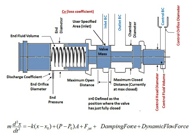
Figure 6.773 - Spool valve model |
The Ball valve and Spool valve model  is given by
  .
.
Theta ( ) is the computed jet angle.