Computational domain
This section explains the preparation of surfaces to create the domain. This is done with the operations splitting, combining and renaming of the surfaces.
The imported geometry consists of multiple separated fluid volumes as shown below:
| port
|
Inlet and Outlet ports |
| rotor
|
Inner and Outer rotors with the crescent chamber |
| island
|
The tips of the crescent shaped gap modelled as stationary fluid volumes
|
Table 6.10 - CAD surfaces
Port Surfaces
- Select CAD Surfaces port in the Geometric Entities Panel.
- Select Split/Combine Geometry or Grid in the Mesh Panel.
- Select Split Disconnected from the Operation drop-down list in the Properties Panel, click Split Disconnected.
- Rename the two new CAD Surfaces port_01 and port_02 as inlet and outlet respectively in the Geometric Entities Panel.
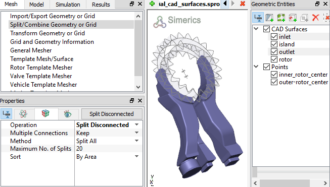
Figure 6.325 - Split of CAD surfaces
Inlet Surfaces
- Select CAD Surfaces inlet in the Geometric Entities Panel.
- Select Split by Angle from the Operation drop-down list in the Properties Panel.
- Enter 75 deg for Angle, click Split by Angle. Twelve new CAD Surfaces entities are created.
- Select CAD Surfaces inlet _03 and inlet_05 in the Geometric Entities Panel. Select Combine from the Operation drop-down list in the Properties Panel and click Combine, rename as inlet_inlet.
- Select CAD Surfaces inlet_01 in the Geometric Entities Panel.
- Select Split by Angle from the Operation drop-down list in the Properties Panel.
- Enter 60 deg for Angle, click Split by Angle. Seven new CAD Surfaces are created.
- Rename inlet _01_02 as inlet_mgi in the Geometric Entities Panel. Select the remaining inlet CAD Surfaces and select Combine from the Operation drop-down list in the Properties Panel, click Combine.
- Rename the combined CAD Surfaces inlet _01_01 as inlet_walls.
|
|
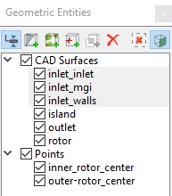
Figure 6.326 - Inlet surfaces
|
Outlet Surfaces
- Select CAD Surfaces outlet in the Geometric Entities Panel.
- Select Split by Angle from the Operation drop-down list in the Properties Panel.
- Enter 60 deg for Angle, click Split by Angle. Ten new CAD Surfaces are created.
- Rename outlet _02 and outlet_03 as outlet_mgi and outlet_outlet respectively in the Geometric Entities Panel.
- Select the remaining outlet CAD Surfaces and select Combine from the Operation drop-down list in the Properties Panel, click Combine.
- Rename the combined CAD Surfaces outlet_01 as outlet_walls.
|
|
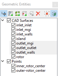
Figure 6.327 - Outlet surfaces
|
Rotor Surfaces
- Select CAD Surfaces rotor in the Geometric Entities Panel.
- Select Split by Angle from the Operation drop-down list in the Properties Panel.
- Enter 75 deg for Angle, click Split by Angle. Four new CAD Surfaces are created.
- Rename the CAD Surfaces rotor_01, rotor_02, rotor_03 and rotor_04 as outer_rotor, inner_rotor, crescent_OD and crescent_ID respectively.
|
|
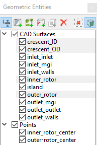
Figure 6.328 - Rotor surfaces
|
Island Surfaces
- Select CAD Surfaces island in the Geometric Entities Panel.
- Select Split Disconnected from the Operation drop-down list in the Properties Panel. Two new CAD Surfaces are created.
- Select CAD Surfaces island_01 and island_02 in the Geometric Entities Panel.
- Select Split by Angle from the Operation drop-down list in the Properties Panel.
- Enter 30 deg for Angle, click Split by Angle. Thirteen new CAD Surfaces are created.
- Select CAD Surfaces as shown in Table 6.11 in the Geometric Entities Panel. Select Combine from the Operation drop-down list and click Combine in the Properties Panel.
- Rename the combined CAD Surfaces with corresponding names as shown in Table 6.11.
- Select the remaining island CAD Surfaces and select Combine from the Operation drop-down list in the Properties Panel.
- Click Combine and rename the combined CAD Surfaces as island_walls.
|
|
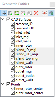
Figure 6.329 - Island surfaces
|
| island_01_01 and island_02_02 |
island_OD_mgi
|
| island_01_02 and island_02_01 |
island_ID_mgi
|
| island_01_03 and island_02_04 |
island_top_mgi
|
Table 6.11 - Combine-CAD surfaces