Building the Mesh
This section describes the procedure for preparing the mesh for the crescent pump. The Rotor Template Mesher is used for creating the rotor-crescent chamber mesh and the General Mesher is used for the inlet, outlet and the island meshes.
Inlet and Outlet
- Select General Mesher in the Mesh Panel.
- Select CAD Surfaces inlet_inlet, inlet_mgi, Inlet_walls, outlet_mgi, outlet_outlet, and outlet_walls in the Geometric Entities Panel and click Add Surfaces
 for CAD Surfaces in the Properties Panel. for CAD Surfaces in the Properties Panel.
- Enter Maximum Cell Size as 0.01, Minimum Cell Size as 0.001 and Cell Size on Surfaces as 0.005.
- Click Create Mesh. A new mesh mesh is created under Built Meshes in the Geometric Entities Panel.
- The meshed volumes inlet and outlet are generated under Volumes.
|
|
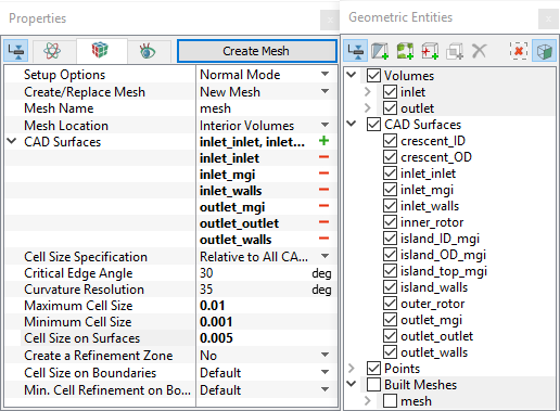
Figure 6.330 - Inlet and Outlet mesh settings
|
Island
- Select General Mesher in the Mesh Panel.
- Select CAD Surfaces island_ID_mgi, island_OD_mgi, island_top_mgi and island_walls in the Geometric Entities Panel and click Add Surfaces for CAD Surfaces in the Properties Panel.
- Enter Maximum Cell Size as 0.01, Minimum Cell Size as 0.001 and Cell Size on Surfaces as 0.005 in the Properties Panel.
- Click Create Mesh. A new mesh island is created under Built Meshes in the Geometric Entities Panel.
- Rename generated volumes island and island_1 as outlet_island and inlet_island respectively under Volumes.
|
|
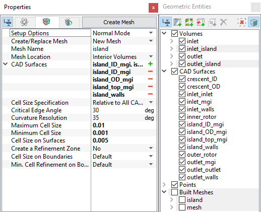
Figure 6.331 - Island mesh settings
|
| ´ |
Note: Two connected Volumes, such as the inlet and island, or island and outlet should not be meshed together using the General Mesher.
They can be, but it will create sub-features on the common surfaces. |
Rotor Mesh
- Select Rotor Template Mesher in the Mesh Panel.
- Select Crescent from the Rotor Type drop-down list in the Properties Panel.
- Select CAD Surfaces inner_rotor in the Geometric Entities Panel, click Add Surfaces for Inner Rotor in the Properties Panel. Similarly select CAD Surfaces outer_rotor, crescent_ID and crescent_OD, click Add Surfaces for Outer Rotor, Crescent Inside Wall and Crescent Outside Wall respectively.
-
Enter the parameters as follows.
-
Number of Inner Teeth: 17
-
Number of Outer Teeth: 21
-
Rotational Axis Vector: 0,0,1
-
Inner Rotor Center: 0, 0, -0.0237
-
Outer Rotor Center: 0, 0.0075, -0.0237
-
Click Build Crescent Mesh. The new mesh crescent is created under Built Meshes in the Geometric Entities Panel.
- The meshed volume crescent is generated under Volumes.
|
|
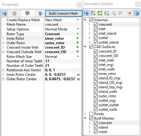
Figure 6.332 - Rotor mesh settings
|
| |
Note:
- The parameters Number of Inner Teeth and Number of Outer Teeth , does not have any effect on that actual number of teeth generated by the Rotor Template Mesher. It is only used during the simulation to compute the time-step parameters, but may be specified during the mesh creation.
- For better refinement of the teeth mesh, select User Input under Rotor Mesh Size, and adjust the parameters Points in Rotational Direction, Points in Radial Direction, and Points in Axial Direction.
|
The mesh created for the fluid domain is shown below.
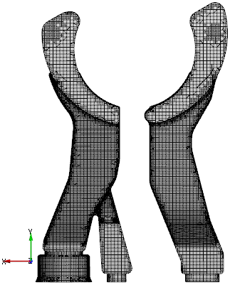
Figure 6.333 - Inlet and Outlet mesh
|
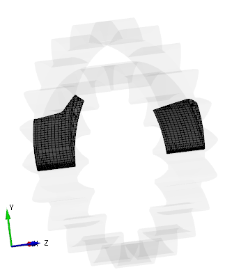
Figure 6.334 - Island mesh
|
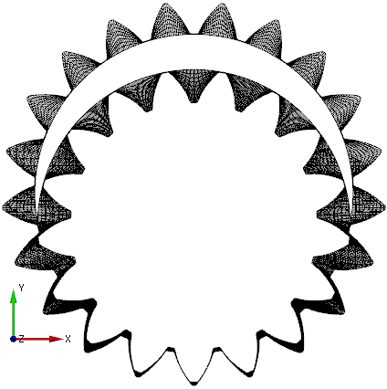
Figure 6.335 - Rotor mesh
|
Create interfaces
In this section, the Mismatched Grid Interfaces (MGIs) are generated between boundaries.
The steps to create the MGI are shown below:
- Geometric Entities Panel > Volumes > Boundaries, select Boundaries as shown in Table 6.12.
- Click Connect Selected Boundaries via MGI
 to create the MGI entities refer, Figure 6.336.
A group display of entities can be viewed using the Group Entities by Volumes/Types  in the Geometric Entities Panel toolbar.
| Pumping chamber, inlet ports, outlet ports, and island top |
inlet_mgi, outlet_mgi, island_top_mgi, island_top_mgi_1 and mgi_rotor_ports_2 |
MGI01 |
| Outside crescent and island |
island_OD_mgi, island_OD_mgi_1 , and crescent_outside |
MGI02 |
| Inside crescent, island, rotor chamber, and volute |
island_ID_mgi, island_ID_mgi_1, and crescent_inside |
MGI03 |
Table 6.12 - Creating interfaces
The new entities are created under MGI in Volumes refer, Figure 6.337.
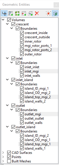
Figure 6.336 - Pumping chamber, inlet ports, outlet ports and island top
|
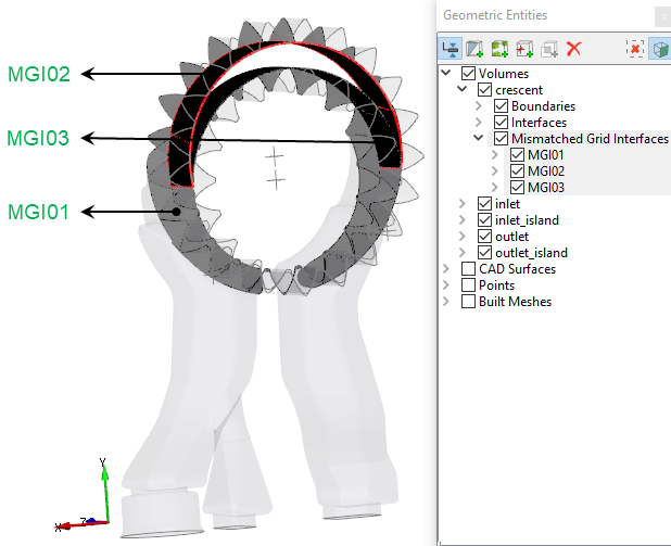
Figure 6.337 - Created interfaces
|
| |
Note: If MGIs are created by connecting the wrong boundaries, delete the created MGIs by clicking on Delete Selected Geometric Entity  and then recreate the MGIs. and then recreate the MGIs.
|