6.5.1 Geometry and Domain
The simulation of the crescent pump requires understanding of the geometry and the fluid domain enclosed by the surfaces of the pump. The general fluid volume of the crescent pump and prerequisite steps, before taking into Simerics-MP+, are described here.
Prerequisite steps
-
The fluid volumes for the crescent pump must be created such that the pumping chamber (the fluid volume between the rotor surfaces) is separated from the inlet and outlet ports.
-
The hardware contains a metal spacer part which occupies the central region of the crescent shaped gap. The tips of the gap must be modelled as stationary fluid volumes called the inlet island and outlet island.
-
For crescent rotor volume, the template requires inner rotor and outer rotor surfaces to be imported. Since the inner rotor drives the outer rotor, it is important that the inner rotor has to be rotated in the CAD to “contact” the outer rotor. Here, “contact” indicates a small clearance (order of 5 microns), since Simerics-MP+ does not allow metal-to-metal contact.
-
The template creates leakage gaps based on the values provided. Hence, the fluid volumes should be imported without clearances.

Figure 6.288 - Crescent Pump - Ports |

Figure 6.289 - Crescent Pump - Rotors |

Figure 6.290 - Crescent - Crescent Walls |
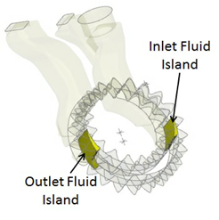
Figure 6.291 - Crescent - Islands |
Fluid Domain
The fluid volume in a crescent pump is defined by CAD Surfaces which enclose them. The crescent model primarily consists of the following volumes: Inlet, Crescent, Islands and Outlet.
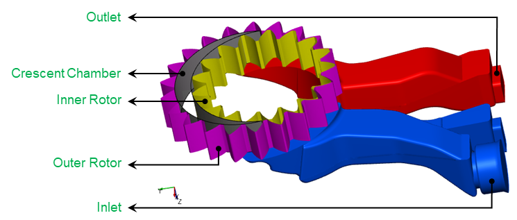
Figure 6.292 - Crescent - Introduction
Inlet: The fluid enters the pump through the inlet boundary. Pressure is generally specified as a boundary condition at the inlet, while the other surfaces of the inlet volume are treated as walls.
Crescent: The fluid volume between the arc-shaped walls which closely fit with the inner and outer rotors.
Inlet and Outlet Island: Stationary volumes that connect the inlet/outlet ports to the crescent chamber.
Outlet: The fluid exits the pump at the outlet boundary. Pressure is generally specified as a boundary condition at the outlet, while the other surfaces of the outlet volume are treated as walls.
For an example of the crescent pump simulation, refer Crescent Pump Tutorial.