|
You are here: Fluid Machinery Templates and Tutorials > External Gear Pump > External Gear Pump Tutorial > Computational domain
|
Computational domain
This section explains the preparation of surfaces to create the domain. This is done with the operations splitting, combining and renaming of the surfaces.

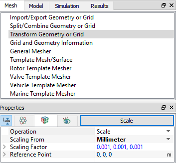
| ´ | Note: Simerics-MP+ assumes all dimensions are in m. Scaling is applied every time the Scale button is clicked in the Mesh Panel. Therefore geometries are only scaled once. |
Pump Surfaces
- Select CAD Surfaces gear_pump in the Geometric Entities Panel.
- Select Split/Combine Geometry or Grid in the Mesh Panel.
- Select Split Disconnected from the Operation drop-down list in the Properties Panel, click Split Disconnected.
-
Rename the five new CAD Surfaces gear_pump_01, gear_pump_02, gear_pump_03, gear_pump_04 and gear_pump_05 as inlet, outlet, drive_gear, slave_gear and shroud respectively in the Geometric Entities Panel.
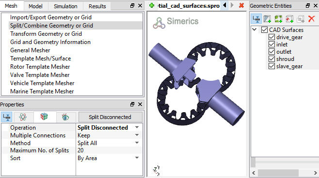
Figure 6.165 - Split of CAD surfaces
Inlet Surfaces
|
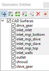
Figure 6.166 - Inlet surfaces |
Rotor Surfaces
|
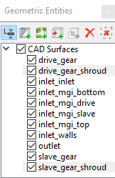
Figure 6.167 - Rotor surfaces |
Outlet Surfaces
|
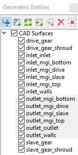
Figure 6.168 - Outlet surfaces |