中文 English

Building the Mesh

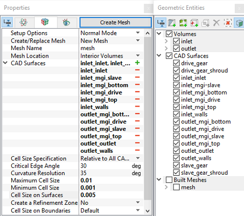
This section describes the step-by-step procedure for preparing the mesh for the external gear pump. The Rotor Template Mesher is used for creating the gear mesh and the General Mesher is used for the inlet and the outlet.

Inlet and Outlet
  1. Select General Mesher in the Mesh Panel.
  2. Select CAD Surfaces inlet_inlet, inlet_mgi_bottom, inlet_mgi_slave, inlet_mgi_drive, inlet_mgi_top, inlet_walls, outlet_mgi_bottom, outlet_mgi_drive, outlet_mgi_slave, outlet_mgi_top, outlet_outlet and outlet_walls in the Geometric Entities Panel and click Add Surfaces icon for CAD Surfaces in the Properties Panel.
  3. Enter Maximum Cell Size as 0.01, Minimum Cell Size as 0.001 and Cell Size on Surfaces as 0.005.
  4. Click Create Mesh. A new mesh mesh is created under Built Meshes in the Geometric Entities Panel.
  5. To refine the interfaces, select mesh from Built Meshes and inlet_mgi_bottom, inlet_mgi_drive, inlet_mgi_slave, inlet_mgi_top, outlet_mgi_bottom, outlet_mgi_drive, outlet_mgi_slave, outlet_mgi_top from CAD Surfaces.

  6. Select User Input from the Cell Size on Boundaries drop-down list, enter 0.0025 for Size in the Properties Panel.
  7. Click Create Mesh to update mesh under Built Meshes in the Geometric Entities Panel.
  8. The meshed volumes inlet and outlet are generated under Volumes.


Figure 6.169 - Inlet and Outlet mesh settings

Rotor
  1. Select Rotor Template Mesher in the Mesh Panel.
  2. Select External Gear for Rotor Type drop-down list in the Properties Panel.
  3. Select CAD Surfaces drive_gear in the Geometric Entities Panel, click Add Surfaces icon for Drive Gear in the Properties Panel. Similarly, select CAD Surfaces drive_gear_shroud, slave_gear and slave_gear_shroud and click Add Surfaces for Drive Gear Outer Boundary, Slave Gear and Slave Gear Outer Boundary respectively.
  4. Enter the parameters as follows.

    • Drive Gear Rotational Axis Vector: 0, 0, 1

    • Drive Gear Center: 0, 0, 0 m

    • Slave Gear Center: 0, -0.042, 0 m

  5. Click Build Gear Mesh. The new mesh gear is created under Built Meshes in the Geometric Entities Panel.
  6. The meshed volume gear is generated under Volumes.


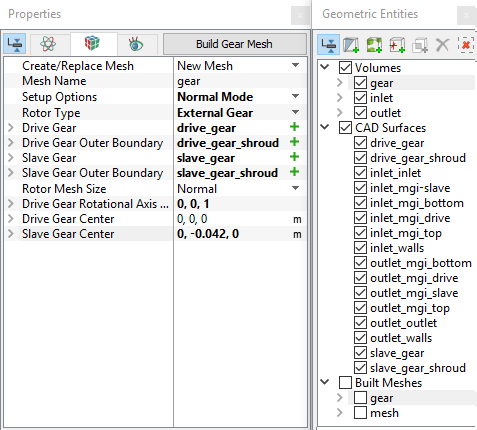
Figure 6.170 - Rotor mesh settings

´

Note:

  • The imported geometry does not include any leakage gap by default. The parameters for the gaps can be adjusted by selecting Advanced Mode under Setup Options in the Properties Panel.
  • Refinement of the mesh can be done by specifying the number of cells in the Rotational, Radial and Axial Directions. For refinement of the teeth mesh in the rotational direction, select User Input under Rotor Mesh Size, expand it and specify the Cells in Rotational Direction as 720.


The mesh created for the fluid domain is shown below.

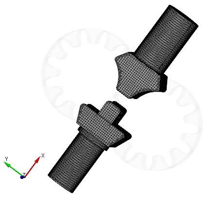
Figure 6.171 - Inlet and Outlet mesh


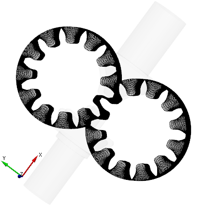
Figure 6.172 - Rotor mesh
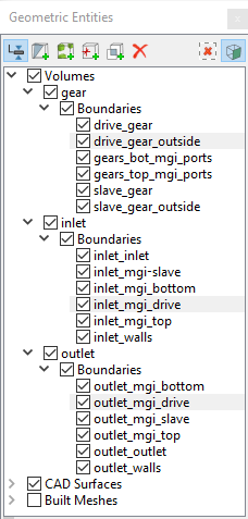
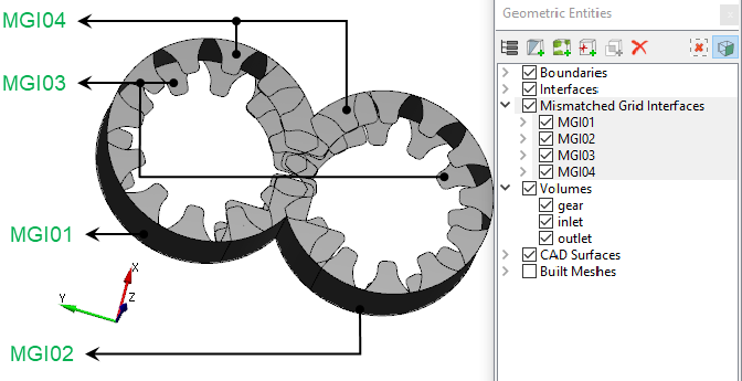
Create interfaces

In this section, the Mismatched Grid Interfaces (MGIs) are generated between boundaries.

The steps to create the MGIs are shown below:

  1. Geometric Entities Panel > Volumes > Boundaries, select Boundaries as shown in Table 6.3.
  2. Click Connect Selected Boundaries via MGI icon to create the MGI entities as shown in Figure 6.173.

A group display of entities can be viewed using the Group Entities by Volumes/Types icon in Geometric Entities Panel toolbar.

Connecting interfaces Boundaries Entity
Drive gear, inlet, and outlet drive_gear_outside, inlet_mgi_drive and outlet_mgi_drive MGI01
Slave gear, inlet, and outlet inlet_mgi_slave, outlet_mgi_slave and slave_gear_outside MGI02
Bottom of the pumping chamber, inlet, and outlet gear_bot_mgi_ports, inlet_mgi_bottom and outlet_mgi_bottom MGI03
Top of the pumping chamber, inlet, and outlet  gear_top_mgi_ports, inlet_mgi_top and outlet_mgi_top MGI04

Table 6.3 - Creating interfaces

The new entities are created under MGI in Volumes (refer, Figure 6.174).

Figure 6.173 - Connecting drive gear, inlet, and outlet


Figure 6.174 - Created interfaces


Note: If MGIs are created by connecting the wrong boundaries, delete the created MGIs by clicking on Delete Selected Geometric Entity icon and then recreate the MGIs.


Copyright © 2023 Simerics Inc.,