中文 English

Computational Domain

This section explains the preparation of surfaces to create the domain. This is done with the operations splitting, combining and renaming of the surfaces. The gear surfaces are already split and named as gear1, gear2 and gear3, as shown in Figure 6.911. The surface preparation of inlet and outlet geometry are explained below.


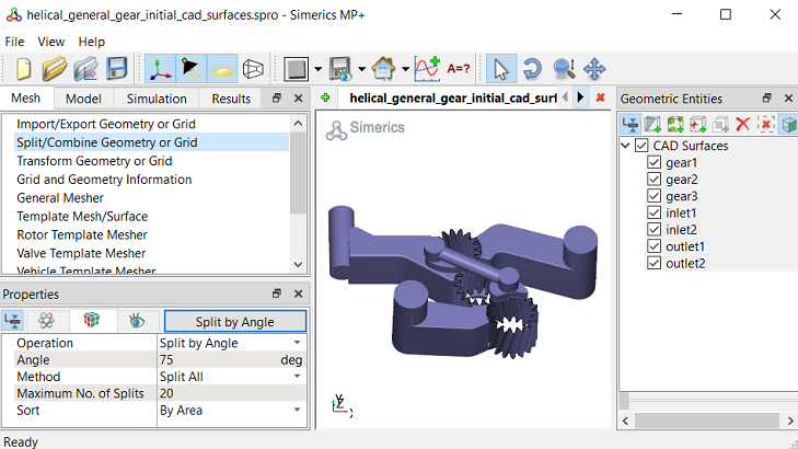
Figure 6.911 - Computational domain
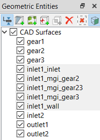

Inlet1 Surfaces
  1. Select CAD Surfaces inlet1 in the Geometric Entities Panel.
  2. Select Split by Angle from the Operation drop-down list in the Properties Panel.
  3. Enter 75 deg for Angle, click Split by Angle. Eight new CAD Surfaces are created.
  4. Rename CAD Surfaces inlet1_03, inlet1_04, inlet1_05, inlet1_06 as inlet1_mgi_gear3, inlet1_inlet, inlet1_mgi_gear2, inlet1_mgi_gear23 respectively in the Geometric Entities Panel.
  5. Select the remaining inlet1 CAD Surfaces and select Combine from the Operation drop-down list in the Properties Panel, click Combine.
  6. Rename the combined CAD Surfaces as inlet1_wall.


Figure 6.912 - Inlet1 surfaces

Inlet2 Surfaces
  1. Select CAD Surfaces inlet2 in the Geometric Entities Panel.
  2. Select Split by Angle from the Operation drop-down list in the Properties Panel.
  3. Enter 75deg for Angle and enter 5 for Maximum No. of Splits, click Split by Angle. Six new CAD Surfaces are created.
  4. Rename CAD Surfaces inlet2_03, inlet2_04, inlet2_05 as inlet2_mgi_gear1, inlet2_inlet and inlet2_mgi_gear12 respectively in the Geometric Entities Panel.
  5. Select the remaining inlet2 CAD Surfaces and select Combine from the Operation drop-down list in the Properties Panel, click Combine.
  6. Rename the combined CAD Surfaces as inlet2_wall.


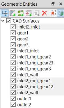
Figure 6.913 - Inlet2 surfaces

Outlet1 Surfaces
  1. Select CAD Surfaces outlet1 in the Geometric Entities Panel.
  2. Select Split by Angle from the Operation drop-down list in the Properties Panel.
  3. Enter 75deg for Angle and enter 5 for Maximum No. of Splits, click Split by Angle. Six new CAD Surfaces are created.
  4. Rename CAD Surfaces outlet1_04 and outlet1_05 as outlet1_mgi_gear1 and outlet1_mgi_gear3 respectively in the Geometric Entities Panel.
  5. Select the remaining outlet1CAD Surfaces and select Combine from the Operation drop-down list in the Properties Panel, click Combine.
  6. Rename the combined CAD Surfaces as outlet1_wall.


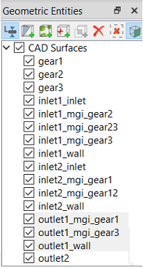
Figure 6.914 - Outlet1 surfaces

Outlet2 Surfaces
  1. Select CAD Surfaces outlet2 in the Geometric Entities Panel.
  2. Select Split by Angle from the Operation drop-down list in the Properties Panel.
  3. Enter 75 deg for Angle , click Split by Angle. Eleven new CAD Surfaces are created in the Geometric Entities Panel.
  4. Rename the CAD Surfaces outlet2_04, outlet2_05, outlet2_06 and outlet_07 as outlet2_mgi_gear1, outlet2_mgi_gear12, outlet2_outlet and outlet2_mgi_gear2 respectively in the Geometric Entities Panel.

  5. Select CAD Surfaces outlet2_01 in the Geometric Entities Panel.
  6. Select Split by Angle from the Operation drop-down list in the Properties Panel.
  7. Enter 2 deg for Angle and enter 5 for Maximum No. of Splits, click Split by Angle. Six new CAD Surfaces are created in the Geometric Entities Panel.
  8. Rename the CAD Surfaces outlet2_01_04 as outlet2_mgi_outlet1.

  9. Select the remaining outlet2 CAD Surfaces and select Combine from the Operation drop-down list in the Properties Panel, click Combine.
  10. Rename the combined CAD Surfaces as outlet2_wall.


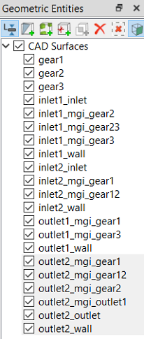
Figure 6.915 - Outlet2 surfaces


Copyright © 2023 Simerics Inc.,