|
You are here: Fluid Machinery Templates and Tutorials > General Gear > General Gear Tutorials > Building the Mesh
|
Building the Mesh
This section describes the step-by-step procedure for preparing the mesh for the helical gear pump. The Rotor Template Mesher is used for creating the gear mesh and the General Mesher is used for the inlets and the outlets.
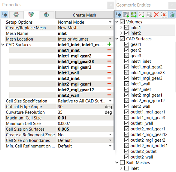
Outlet1 and Outlet2
|
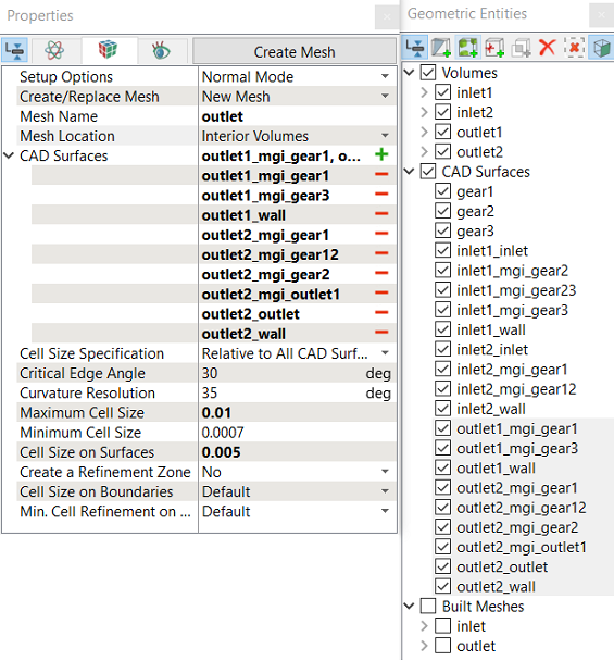
Figure 6.917 - Outlet1 and Outlet2 mesh settings |
Gear
Gear1 Parameters
Gear2 Parameters
Gear3 Parameters
|
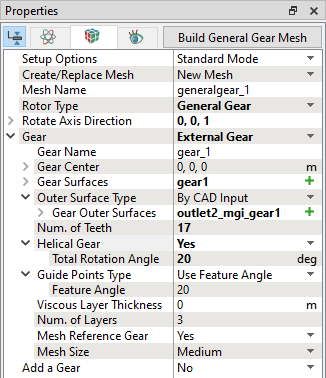
Figure 6.918 - Gear1 mesh settings
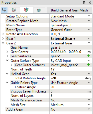
Figure 6.919 - Gear2 mesh settings
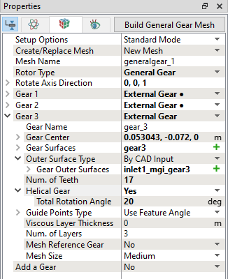
Figure 6.920 - Gear3 mesh settings |
| ´ | Note: In the Rotor Template Mesher, the Outer Surface Type has three options to model the rotor chamber. First option is By CAD Input, this requires CAD Surfaces as a input, second option is By Radius, this requires input of radius, and third option is By Tip Gap, this requires Tip Gap Size in m. |
The mesh created for the fluid domain is shown below.
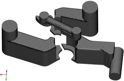
Figure 6.921 - Inlet and Outlet mesh |
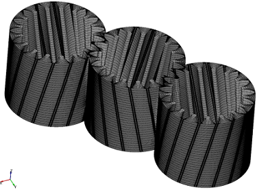
Figure 6.922 - Gear mesh |
|
Note: The mesh can be edited/replaced by selecting required volume under Built Meshes and modify the mesh parameters in the Properties Panel. Click Create Mesh to reflect the changes. |
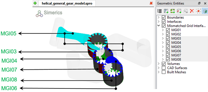
Default MGI Creation in Template Mesher
- The Rotor Template Mesher creates interfaces between the gears automatically.
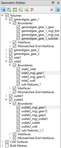
- Two Mismatched Grid Interfaces (MGIs), MGI01 and MGI02 are created interfacing the generalgear_gear1, generalgear_gear2 and generalgear_gear3 under Volumes.
-
These MGIs are created using some default projection tolerance. Do not change any of these settings especially for default MGIs.
Create interfacesIn this section, the Mismatched Grid Interfaces (MGIs) are generated between boundaries. The steps to create the MGIs are shown below:
A group display of entities can be viewed using the Group Entities by Volumes/Types
Table 6.45 - Creating interfaces
The new entities are created under MGI in Volumes (refer, Figure 6.924). |
|
Note: If MGIs are created by connecting the wrong boundaries, delete the created MGIs by clicking on Delete Selected Geometric Entity |