中文 English
You are here: Fluid Machinery Templates and Tutorials > General Gear > General Gear Tutorials > Defining Physics and Conditions

Defining Physics and Conditions

The physics and conditions are specified as follows:

Adding Modules
  1. Click Select Modules in the Model Panel. The Physical Model Selection dialog box opens.
  2. General Gear is automatically added to the Model Panel by the Rotor Template Mesher.
  3. Select Turbulence under Available Modules and click Add. Similarly, select Cavitation under Available Modules and click Add
  4. Click Close to close the Physical Model Selection dialog box.


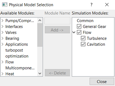
Figure 6.925 - Adding modules

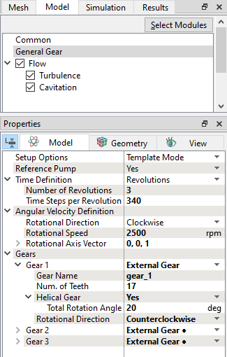
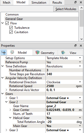
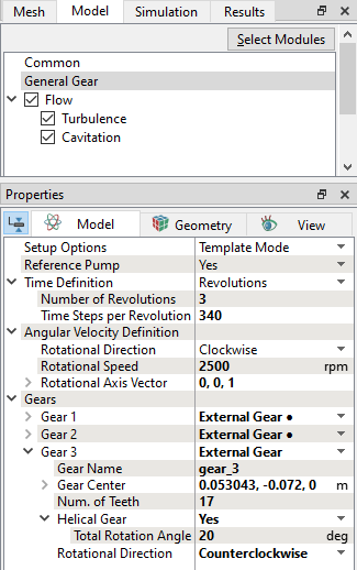
General Operating Parameters
  1. Select General Gear in the Model Panel.
  2. Enter Number of Revolutions and Time Steps Per Revolution to 3 and 340 respectively for the Time Definition in the Model Tab of Properties Panel.
  3. Enter the parameters for the Angular Velocity Definition as follows.

    • Rotational Direction: Clockwise

    • Rotational Speed: 2500 rpm

    • Rotational Axis Vector: 0,0,1

  4. Enter the parameters for the Gear1, Gear2 and Gear3 as shown in Figure 6.927, Figure 6.928 and Figure 6.929.

    • Rotational Direction: Counterclockwise for Gear 1 list.

    • Main Gear: Yes for Gear2 list.

    • Rotational Direction: Counterclockwise for Gear 3 list.


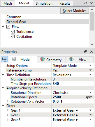
Figure 6.926 - Operating parameters

  Note: Provide speed and angular velocity definition parameters with respect to Gear 2, as it is set as main gear. The Rotational Direction for Gear 2 is automatically detected by the Angular Velocity Definition settings.
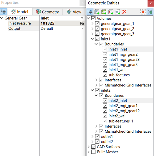
 

Figure 6.927 - Gear 1


Figure 6.928 - Gear 2


Figure 6.929 - Gear 3


Boundary Conditions

The boundary conditions are specified as follows:

Inlet
  1. Select inlet1_inlet and inlet2_inlet from the Boundaries list under Volumes in the Geometric Entities Panel.
  2. Select Inlet from the Gear drop-down list in the Model Tab of Properties Panel.
  3. Enter Inlet Pressure as 101325 Pa.


Figure 6.930 - Inlet conditions

Outlet
  1. Select outlet2_outlet from the Boundaries list in the Geometric Entities Panel.

  2. Select Outlet from the Gear drop-down list in the Model Tab of Properties Panel.
  3. Enter Outlet Pressure as 500000 Pa.


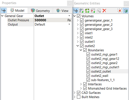
Figure 6.931 - Outlet conditions

´ Note: The gear boundary conditions are assigned automatically by Rotor Template Mesher.
Fluid Properties
  1. Select Volumes in the Geometric Entities Panel.
  2. Select Model Tab of Properties Panel.

  3. Enter the parameters for Property list as follows.

    • Material: Oil
    • Dynamic Viscosity: 0.007 Pa-s
    • Density: 800 kg/m3
    • Liquid Bulk Modulus(B0): 1.5e+09 Pa
    • Liquid Reference Pressure: 101325 Pa

    • Saturation Pressure: 400 Pa

  4. Enter the parameters for Operating Conditions list as follows.

    • Gas Mass Fraction: 9e-5
    • Operating Temperature: 300 K
    • Starting Pressure: 101325 Pa
 

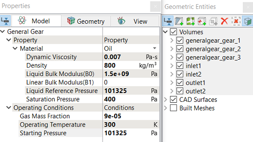
Figure 6.932 - Fluid properties


Copyright © 2023 Simerics Inc.,