6.2.1 Geometry and Domain
The simulation of the gerotor pump requires understanding of the geometry and the fluid domain enclosed by the surfaces of the pump. The general fluid volume of the gerotor pump and prerequisite steps, before taking into Simerics-MP+, are described here.
Prerequisite steps
- The fluid volume for the gerotor pump consists of inlet port, outlet port, rotor and grooves. Except the rotor volume, other volumes are imported from any CAD package in .stl format into Simerics-MP+.
- For rotor volume, the template requires inner and outer gear surfaces to be imported.
- The template creates leakage gaps based on the values provided. However, if the imported fluid volumes have different gaps than the actual, they should be adjusted by projecting the surfaces.
Fluid Domain
The fluid volume in a gerotor pump is defined by CAD Surfaces which enclose them. The gerotor pump model primarily consists of the following volumes: Inlet, Rotor, Outlet and occasionally Grooves (adjacent to the outlet port), as shown in Figure 6.68
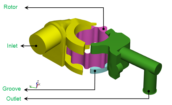
Inlet: The fluid enters the pump through the inlet boundary. Pressure is generally specified as a boundary condition at the inlet, while the other surfaces of the inlet volume are treated as walls
Rotor: The fluid volume between the outer and inner rotors is called the rotor. The fluid gets trapped and compressed in this volume.
Groove: This volume allows/regulates flow to the outlet when there is an excess of fluid. It thereby prevents noise when the trapped fluid is being compressed and cannot escape into the outlet.
Outlet: The fluid exits the pump at the outlet boundary. Pressure is generally specified as a boundary condition at the outlet , while the other surfaces of the outlet volume are treated as walls.
For an example of the gerotor pump simulation, refer Gerotor Pump Tutorial.