中文 English

Computational domain

This section explains the preparation of surfaces to create the domain. This is done with the operations splitting, combining and renaming of the surfaces.

Pump Surfaces
  1. Select Split/Combine Geometry or Grid in the Mesh Panel.
  2. Select CAD Surfaces gerotor in the Geometric Entities Panel.
  3. Select Split Disconnected from the Operation drop-down list in the Properties Panel, click Split Disconnected.
  4. Rename the four new CAD Surfaces gerotor_1, gerotor_2, gerotor_3 and gerotor_4 as inlet, outlet, rotor and groove respectively in the Geometric Entities Panel.

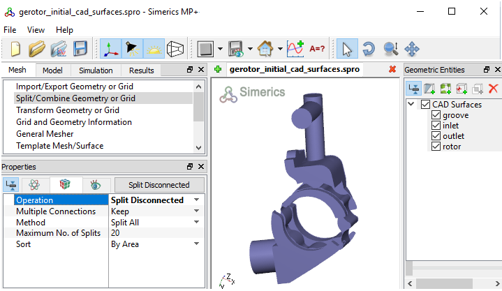
    Figure 6.104 - Split of CAD surfaces


Inlet Surfaces
  1. Select CAD Surfaces inlet in the Geometric Entities Panel.
  2. Select Split by Angle from the Operation drop-down list in the Properties Panel.
  3. Enter 75 deg for Angle, click Split by Angle. Eight new CAD Surfaces are created.
  4. Rename CAD Surfaces inlet_4, inlet_5 and inlet_6 as inlet_mgi_top, inlet_mgi_bot and inlet_inlet respectively in the Geometric Entities Panel.
  5. Select the remaining CAD Surfaces and select Combine from the Operation drop-down list in the Properties Panel, click Combine.
  6. Rename the combined CAD Surfaces as inlet_walls.
 

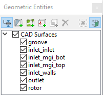
Figure 6.105 - Inlet surfaces


Rotor Surfaces
  1. Select CAD Surfaces rotor in the Geometric Entities Panel.
  2. Select Split by Angle from the Operation drop-down list in the Properties Panel.
  3. Enter 75 deg for Angle, click Split by Angle. Four new CAD Surfaces entities rotor_01 to rotor_04 are created in the Geometric Entities Panel.
  4. Rename CAD Surfaces rotor_01 and rotor_02 as outer_rotor and  inner_rotor respectively.
  5. Select the remaining CAD Surfaces, click Delete Selected Geometric Entity icon to delete surfaces.
 

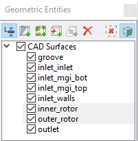
Figure 6.106 - Rotor surfaces


Outlet Surfaces
  1. Select CAD Surfaces outlet in the Geometric Entities Panel.
  2. Select Split by Angle from the Operation drop-down list in the Properties Panel.
  3. Enter 75 deg for Angle, click Split by Angle. Ten new CAD Surfaces are created in the Geometric Entities Panel.
  4. Rename the CAD Surfaces outlet_03 and outlet_07 as outlet_mgi_top and outlet_outlet respectively.
  5. Select the remaining outlet CAD Surfaces and select Combine from the Operation drop-down list in the Properties Panel, click Combine.
  6. Rename the combined CAD Surfaces as outlet_walls.
 

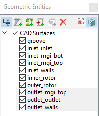
Figure 6.107 - Outlet surfaces


Groove Surfaces
  1. Select CAD Surfaces groove in the Geometric Entities Panel.
  2. Select Split by Angle from the Operation drop-down list in the Properties Panel.
  3. Enter 75 deg for Angle, click Split by Angle. Three new CAD Surfaces are created in the Geometric Entities Panel.
  4. Rename the CAD Surfaces groove_02 as groove_mgi.
  5. Select the remaining groove CAD Surfaces and select Combine from the Operation drop-down list in the Properties Panel, click Combine.
  6. Rename the combined CAD Surfaces as groove_walls.
 

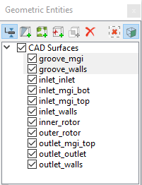
Figure 6.108 - Groove surfaces


´ Note:  Splitting of the surfaces can also be done by mouse selection using the Split by Mouse option from the Method drop-down list in the Geometry Tab of Properties Panel.


Copyright © 2023 Simerics Inc.,