Building the Mesh
This section describes the step-by-step procedure for preparing the mesh for the gerotor pump. The Rotor Template Mesher is used for creating the rotor chamber mesh and the General Mesher is used for creating the mesh for the inlet, outlet and the grooves.
Inlet, Outlet and Groove Meshes
- Select General Mesher in the Mesh Panel.
- Select CAD Surfaces groove_mgi, groove_walls, inlet_inlet, inlet_mgi_top, inlet_mgi_bot, inlet_walls, outlet_mgi_top, outlet_outlet, outlet_walls in the Geometric Entities Panel and click Add Surfaces
 icon for CAD Surfaces in the Properties Panel. icon for CAD Surfaces in the Properties Panel.
- Enter the Maximum Cell Size as 0.01, Minimum Cell Size as 0.001 and Cell Size on Surfaces as 0.005 .
- Click Create Mesh. A new mesh mesh is created under Built Meshes in the Geometric Entities Panel.
-
To refine the interfaces, select mesh from Built Meshes and groove_mgi, inlet_mgi_top, inlet_mgi_bot, outlet_mgi_top from CAD Surfaces.
- Select User Input from Cell Size on Boundaries drop-down list, enter 0.0025 for Size in the Properties Panel. Click Create Mesh to update mesh under Built Meshes in the Geometric Entities Panel.
- The meshed volumes groove, inlet and outlet are generated under Volumes.
|
|
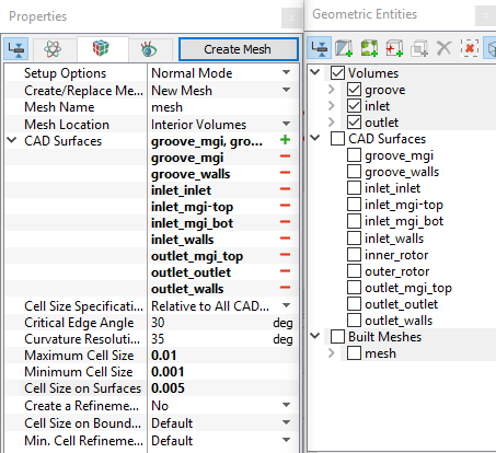
Figure 6.109 - Inlet, Outlet and Groove mesh settings
|
Rotor Chamber Mesh
- Select Rotor Template Mesher in the Mesh Panel.
- Select Advanced Mode for Setup Options and Gerotor for Rotor Type in the Properties Panel.
- Select CAD Surfaces inner_rotor in the Geometric Entities Panel, click Add Surfaces icon for Inner Rotor in the Properties Panel. Similarly select CAD Surfaces outer_rotor and click Add Surfaces icon for Outer Rotor.
-
Enter the parameters as follows.
- Number of Inner Teeth: 8
- Number of Outer Teeth: 9
- Rotational Axis Vector: 0, 0, 1
- Inner Rotor Center: 0, 0, 0
- Outer Rotor Center: 0.003607, 0, 0
- Side Gap Option: Uniform Side Gaps
- Side Leakage Gap: 0.0001
- Gap Inner Radius: 0.02
- Gap Outer Radius: 0.0445
- Click Build Gerotor Mesh. The new mesh gerotor is created under Built Meshes in the Geometric Entities Panel.
- The meshed volumes gerotor and gerotor_gap are generated under Volumes.
|
|
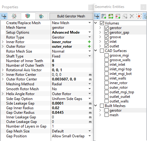
Figure 6.110 - Rotor chamber mesh settings
|
| ´ |
Note:
- The imported geometry does not include any leakage gap by default. The parameters for the gaps can be adjusted by selecting a Advanced Mode under Setup Options in the Properties Panel.
- Refinement of the mesh can be done by specifying the number of Points in the Rotational, Radial and Axial Directions by selecting User Input under Rotor Mesh Size.
|
Default MGI Creation in Template Mesher
- Depending on the leakage gap specifications, the Rotor Template Mesher creates an entity gerotor_gap under Volumes in the Geometric Entities Panel.
- Two Mismatched Grid Interfaces (MGIs), MGI01 and MGI02 are created interfacing the gerotor and gerotor_gap under Volumes.
| |
Note: The mesh can be edited/replaced by selecting it under Built Meshes, and modify the mesh parameters in the Properties Panel. Click Create Mesh to reflect the changes. |
The mesh created for the fluid domain is shown below.
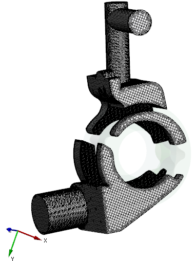
Figure 6.111 - Inlet, Outlet and Groove mesh
|
|
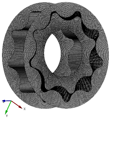
Figure 6.112 - Rotor mesh
|
Create interfaces
In this section, the MGIs are generated between boundaries.
The steps to create the MGIs are shown below:
- Geometric Entities Panel > Volumes > Boundaries, select Boundaries as shown in Table 6.2.
- Click Connect Selected Boundaries via MGI
 icon to create the MGI entities (see, Figure 6.113).
A group display of entities can be viewed using the Group Entities by Volumes/Types  icon inGeometric Entities Panel toolbar.
| Gerotor gap, groove and inlet |
mgi_gap_ports_1, groove_mgi and inlet_mgi_bot
|
MGI03 |
| Gerotor gap, inlet and outlet |
outlet_mgi_top, inlet_mgi_top and mgi_gap_ports_2
|
MGI04 |
Table 6.2 - Creating interfaces
The new entities are created under MGI in Volumes (see, Figure 6.114).
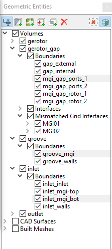
Figure 6.113 - Connecting side gap, Groove and Inlet
|
|
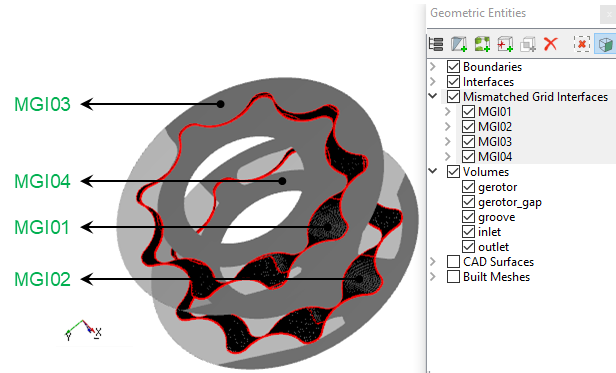
Figure 6.114 - Created interfaces
|
| |
Note: If MGIs are created by connecting the wrong boundaries, delete the created MGIs by clicking on Delete Selected Geometric Entity  icon and then recreate the MGIs. icon and then recreate the MGIs.
|