中文 English
You are here: Fluid Machinery Templates and Tutorials > Gerotor Pump > Gerotor Pump Tutorial > Defining Physics and Conditions

Defining Physics and Conditions

The physics and conditions are specified as follows.

Adding Modules
  1. Click Select Modules in the Model Panel. The Physical Model Selection dialog box opens.
  2. Gerotor is automatically added to the Model Panel by the Rotor Template Mesher.
  3. Select Cavitation under Available Modules and click Add.
  4. Click Close to close the Physical Model Selection dialog box.


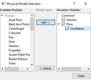
Figure 6.115 - Adding modules

General Operating Parameters
  1. Select Gerotor in the Model Panel.
  2. Enter Number of Revolutions and Time Steps Per Inner Tooth Rotation as 5 and 20 respectively for the Time Definition in the Model Tab of Properties Panel.
  3. Enter the parameters for the Angular Velocity Definition as follows.

    • Rotational Direction: Clockwise

    • Rotational Speed: 4000 rpm

    • Rotational Axis Vector: 0,0,1


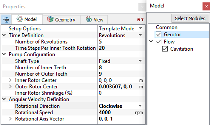
Figure 6.116 - Operating parameters
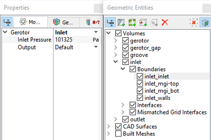
Boundary Conditions

The boundary conditions are specified as follows:

Inlet
  1. Select inlet_inlet from the Boundaries list under Volumes in the Geometric Entities Panel.
  2. Select Inlet from the Gerotor drop-down list in the Model Tab of Properties Panel.
  3. Enter Inlet Pressure as 101325 Pa.


Figure 6.117 - Inlet conditions

Inner and Outer Rotor

  1. The boundary conditions to the inner and the outer rotors are automatically assigned by the Gerotor module.
  2. Click inner_rotor and outer_rotor from Boundaries list in the Geometric Entities Panel. Check the values under the Model Tab of Properties Panel.
  3. The values for the inner_rotor are the same as specified under Gerotor in the Model Panel.
  4. The Rotational Speed of the outer_rotor is calculated by the Gerotor module based on the gear ratio.
Rotating wall in side gaps
  1. Select  mgi_gap_rotor_1 and mgi_gap_rotor_2 from the Boundaries list in the Geometric Entities Panel.
  2. Select Rotating Wall from the Gerotor drop-down list in the Model Tab of Properties Panel.
  3. Enter Rotational Speed as 3777 rpm.


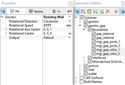
Figure 6.118 - Rotating wall conditions


´ Note:   The Rotational Speed of each rotor boundary (Inner rotor and Outer rotor) is different. Setting an arithmetic mean for the Rotating Wall Boundaries Conditions (BC) could be a good approximation. The Rotational Speed of the Inner rotor is 4000 rpm and the Rotational Speed of the Outer rotor is 3555.5 rpm. Then the arithmetic mean ~3777 rpm would be a good approximation for the Rotating Wall BC.


Outlet
  1. Select  outlet_outlet from the Boundaries list in the Geometric Entities Panel.

  2. Select Outlet from the Gerotor drop-down list in the Model Tab of Properties Panel.
  3. Enter Outlet Pressure as 500000 Pa.
 

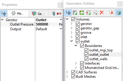
Figure 6.119 - Outlet conditions

Fluid Properties
  1. Select Volumes in the Geometric Entities Panel.
  2. Select Model Tab in the Properties Panel.
  3. Enter the parameters for Property list as follows.

    • Material: Oil
    • Dynamic Viscosity: 0.007 Pa-s
    • Density: 800 kg/m3
    • Liquid Bulk Modulus(B0): 1.5e09 Pa
    • Liquid Reference Pressure: 101325 Pa
    • Saturation Pressure: 400 Pa
  4. Enter the parameters for Operating Conditions list as follows.

    • Gas Mass Fraction9e-05
    • Operating Temperature300 K
    • Starting Pressure: 101325 Pa
 

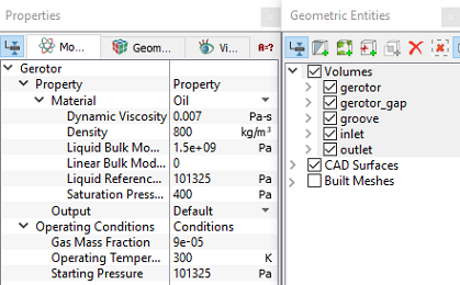
Figure 6.120 - Fluid properties


Copyright © 2023 Simerics Inc.,