|
You are here: Fluid Machinery Templates and Tutorials > Progressive Cavity Pump > Geometry and Domain
|
6.15.1 Geometry and Domain
The simulation of the progressive cavity pump requires understanding of the geometry and the fluid domain enclosed by the surfaces of the pump. The general fluid volume of the progressive cavity pump and prerequisite steps, before taking into Simerics-MP+ are described as follows:
Prerequisite steps
- The fluid volume for the progressive cavity pump consists of inlet port, outlet port and progressive. Except the progressive volume, other volumes are imported from any CAD package in .stl format into Simerics-MP+.
- For progressive volume, the template requires progressive cavity characteristics.
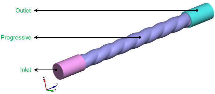
Figure 6.837 - Progressive cavity-Introduction
Fluid Domain
The progressive cavity pump consists of inlet, outlet, stator and rotor.
Inlet: The fluid enters the pump through the inlet boundary. Pressure or flux is generally specified as a boundary condition at the inlet, while the other surfaces of the inlet volume are treated as walls.
Progressive: The fluid volume between the rotor and stator is called progressive. For a rotor volume, the template does not require CAD Surfaces to generate Rotor Chamber Mesh, as in case of other template mesh. The rotor volume is created based on mathematical formulation inside Simerics-MP+.
Outlet: The fluid exits the pump at the outlet boundary. Pressure or flux is generally specified as a boundary condition at the outlet, while the other surfaces of the outlet volume are treated as walls.