|
You are here: Fluid Machinery Templates and Tutorials > Progressive Cavity Pump > Progressive Cavity Pump Tutorial > Contours
|
Contours
The most common contours for the progressive cavity pump simulation are the pressure, and the total gas volume fraction across the domain. The steps to create contours are:
- Click Load Results in the Simulation Panel.
- Select the required result file in the ensuing Load Results dialog box, click Open.
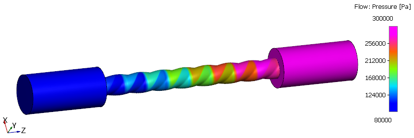
Pressure Contours
- Select Volumes in the Geometric Entities Panel.
- Select Pressure from the Variables list under Variable drop-down list in the Results Panel (see, Figure 6.876). For variables and legends refer, Post-Processing.
- Specify Min as 80000 Pa and Max as 300000 Pa in the Results Panel.
Creating a section
A section is created with the following steps.
- Click Create a Cross-Section
 icon in the Geometric Entities Panel. A new entities Section 01 is created under Derived Surfaces.
 - Select the Section 01 under Derived Surfaces and specify the Type and Position as Plane X and 0 m in the Geometry Tab of Properties Panel.
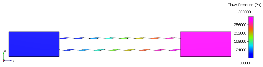
Pressure Contours on Section
- Select Section 01 under Derived Surfaces in the Geometric Entities Panel.
- Select Pressure from the Variables list under Variable drop-down list in the Results Panel (see, Figure 6.877).
- Specify Min as 80000 Pa and Max as 300000 Pa in the Results Panel.
| ´ | Note: Changes to the display, such as legend, contour color, image sizing, transparency can be made under the View Tab of Properties Panel. |