Building the Mesh
This section describes the step-by-step procedure for preparing the mesh for the progressive cavity pump. The Template Mesher is used to create the mesh for the inlet and outlet, and the Rotor Template Mesher is used to create the rotor chamber mesh.
Inlet Mesh
To generate a mesh for an inlet and outlet volume, the cylinder option is used.
General Operating Parameters
- Select Template Mesh/Surface in the Mesh Panel.
- Select Cylinder from the Shape drop down list in Geometry Tab of Properties Panel.
- Enter inlet for Mesh Name.
-
Enter the parameters as follows:
- Reference Point: 0, 0, 0
- 1st Point: 0, 0, -0.1
- Radius: 0.025
- Select User from the Setting drop down list in Geometry Tab of Properties Panel.
-
Enter the parameters as follows:
- Number of Grid in 1st Dir.: 20
- Number of Grid in 2nd Dir.: 20
- Number of Grid in 3rd Dir.: 60
- Click Build Cylinder Mesh. The new mesh inlet is created under Built Meshes in the Geometric Entities Panel.
- The meshed volume inlet is generated under Volumes.
- Rename inlet Boundaries dir_max, dir_min and inlet as inlet_inlet, inlet_mgi and inlet_wall respectively in the Geometric Entities Panel.
|
|
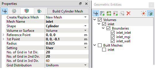
Figure 6.861 - Inlet mesh settings
|
Outlet Mesh
- Select Template Mesh/Surface in the Mesh Panel.
- Select Cylinder from the Shape drop down list in Geometry Tab of Properties Panel.
- Enter outlet for Mesh Name.
-
Enter the parameters as follows:
- Reference Point: 0, 0, 0.24
- 1st Point: 0, 0, 0.34
- Radius: 0.025
- Select User from the Setting drop down list in Geometry Tab of Properties Panel.
-
Enter the parameters as follows:
- Number of Grid in 1st Dir.: 20
- Number of Grid in 2nd Dir.: 20
- Number of Grid in 3rd Dir.: 60
- Click Build Cylinder Mesh. The new mesh outlet is created under Built Meshes in the Geometric Entities Panel.
- The meshed volume outlet is generated under Volumes.
- Rename outlet Boundaries dir_max, dir_min and outlet as outlet_outlet, outlet_mgi and outlet_wall respectively in the Geometric Entities Panel.
|
|
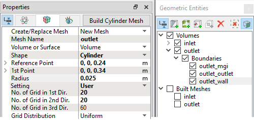
Figure 6.862 - Outlet mesh settings
|
Rotor Chamber Mesh
- Select Rotor Template Mesher in the Mesh Panel.
- Select Advanced Mode for Setup Options and Progressive for Rotor Type in the Properties Panel.
-
Enter the parameters as follows:
- Click Build Progressive Mesh. The new mesh progressive is created under Built Meshes in the Geometric Entities Panel.
- The meshed volume progressive is generated under Volumes.
|
|
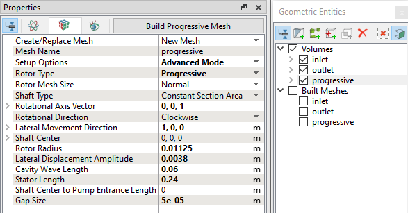
Figure 6.863 - Rotor chamber mesh settings
|
The mesh created for the fluid domain is shown below.
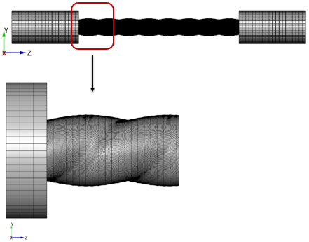
Figure 6.864 - Mesh
|
|
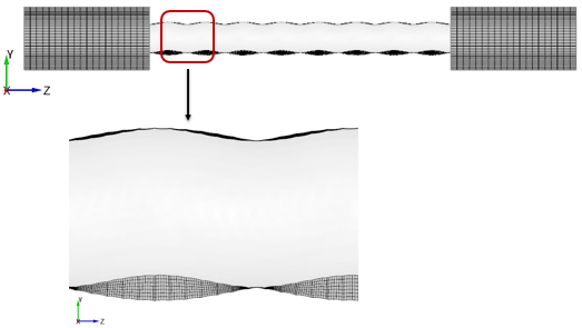
Figure 6.865 - Sectional View - Mesh
|
Create interfaces
In this section, the MGIs are generated between boundaries.
The steps to create the MGIs are shown below:
- Geometric Entities Panel > Volumes > Boundaries, select Boundaries as shown in Table 6.44.
- Click Connect Selected Boundaries via MGI
 icon to create the MGI entities (see, Figure 6.866).
A group display of entities can be viewed using the Group Entities by Volumes/Types  icon in Geometric Entities Panel toolbar.
| Inlet and rotor |
Inlet_mgi and mgi_rotor_port_1 |
MGI01 |
| Outlet and rotor |
outlet_mgi and mgi_gap_ports_2 |
MGI02 |
Table 6.44 - Creating interfaces
The new entities are created under MGI in Volumes (see, Figure 6.867).
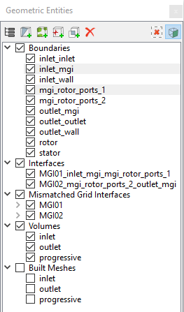
Figure 6.866 - Connecting Rotor and Inlet
|
|
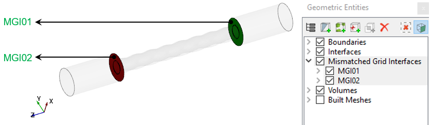
Figure 6.867 - Created interfaces
|
| ´ |
Note: If MGIs are created by connecting the wrong boundaries, delete the created MGIs by clicking on Delete Selected Geometric Entity icon and then recreate the MGIs. icon and then recreate the MGIs.
|