|
You are here: Fluid Machinery Templates and Tutorials > Progressive Cavity Pump > Mesher > Progressive Cavity Meshing
|
Progressive Cavity meshing
This section explains the settings for the progressive cavity mesh generated using the Rotor Template Mesher. This involves selection of the surfaces, directional characteristics of the mesh and other advanced mesh settings.
The parameters related to Progressive meshing can be accessed by setting the Setup Options to Advanced Mode, as shown in Figure 6.840.

Rotor Mesh SizeThis allows to control the resolution of the mesh created in the progressive cavity chamber, by selecting the specified parameters given below:
|
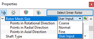

Figure 6.842 - Rotor mesh size-Progressive cavity: Coarse, Fine and Normal
The control parameters associated with User Input (see, Figure 6.841) are:
- Points in Rotational Direction: Corresponds to the number of cell nodes in the rotational direction. The number of control cells in this direction is (Points in Rotational Direction-1).
- Points in Radial Direction: Corresponds to the number of cell nodes in the radial direction. The number of control cells in this direction is (Points in Radial Direction-1).
- Points in Axial Direction: Corresponds to the number of cell nodes in the axial direction from the bottom to the top of the pumping chamber. The number of control cells in this direction is (Points in Axial Direction-1).

Figure 6.843 - User input-Progressive
Shaft TypeThis feature creates a progressive cavity by selecting one of the following parameters:
|
Figure 6.844 - Shaft type |

|
Figure 6.845 - Constant section area |
Figure 6.846 - Variable section area |


Rotational Axis Vector
This vector is aligned with the axis of rotation of the rotor/stator in the neutral position. Specify the vector in terms of  co-ordinates.

Figure 6.847 - Rotational axis vector-Progressive cavity
The Rotational Axis Vector, combined with Shaft Center, Rotor Radius, Cavity Wave Length, Stator Length defines the shape of the rotor when using a Constant Section Area or Variable Section Area.
- The subsequent motion of a rotor with a Constant Section Area is a combination of rotation and translation, based on the Rotational Axis Vector, Rotational Direction and Rotational Speed combined with the Lateral Movement Direction and Lateral Displacement Amplitude.
- The motion of the rotor with a Variable Section Area includes a tilting motion, based on the Lateral Movement Direction and Lateral Displacement Amplitude relative to the Shaft Center.
|
Note: While the Rotational Axis Vector can be reset under Progressive Cavity parameters, it will most likely create problems during rotation. It is therefore recommended to use the correct value during meshing. |
Rotational Direction
This determines the Clockwise or Counterclockwise rotation of an entity relative to the stationary (lab) frame of reference, from the perspective of an observer with the Rotational Axis Vector aimed straight on. This direction dictates the direction of twist of the rotor created during meshing.
|
Note: The parameter Rotational Direction can be reset under Progressive Cavity parameters and will change the twist and the direction of rotation during the simulation. |
Lateral Movement Direction
This specifies the direction in which the rotor surface oscillates relative to the stator surface. This will dictate the clearance used during the simulation. A reasonable value should be used during meshing in order to achieve an optimized mesh.
Shaft Center
This is used to generate the geometry during meshing.
For Constant Section Area, this corresponds to any point along the centerline of the rotor/stator.
For Variable Section Area, the Shaft Center, in conjunction with the Lateral Displacement Amplitude and Shaft Center to Pump Entrance Length also dictates the magnitude of the taper of the rotor, as generated during meshing. This corresponds to the pivot point of the drive shaft.
Rotor Radius
This value dictates the magnitude of rotor radius, as generated during meshing.
For Constant Section Area, this corresponds to the rotor radius at any point along the length of the cavity.
For Variable Section Area, this corresponds to the rotor radius at the pump entrance.
|
Figure 6.848 - Rotor radius |
Figure 6.849 - Progressive cavity |


Lateral Displacement Amplitude
This specifies the magnitude of the lateral displacement of the rotor as the rotor surface oscillates relative to the stator surface. This dictates the magnitude of the lateral spacing in the Lateral Movement Direction between the stator and rotor, as generated during meshing.
For Constant Section Area, this value corresponds to the lateral displacement at any point along the length of the cavity.
For Variable Section Area, this value corresponds to the lateral displacement at the pump entrance.
Cavity Wave Length
This specifies length of two crests in the stator geometry and dictates the wave shape of the rotor and stator in the axial direction generated during meshing.

Figure 6.850 - Cavity wave length
Stator Length
This specifies the length of both the stator and rotor generated during meshing.

Figure 6.851 - Stator length
Shaft Center to Pump Entrance Length
This is the distance between the shaft center and the pump entrance, required to create the geometry creating Variable Section Area.

Figure 6.852 - Shaft center and the pump entrance
For Constant Section Area, this length could technically have any value, but typically is left at the default of zero.
For Variable Section Area, this length, in conjunction with the shaft center and lateral displacement amplitude dictates the magnitude of the taper of the rotor, as generated during meshing. This length must correspond to the distance between the shaft center and the pump inlet.
Gap Size
This specifies the minimum distance between the rotor surface and the stator surface generated during meshing.

Figure 6.853 - Gap size