中文 English

Computational domain

This section explains the preparation of surfaces to create the domain. This is done with the operations splitting, combining and renaming of the surfaces.

Pump Surfaces
  1. Select Split/Combine Geometry or Grid in the Mesh Panel.
  2. Select CAD Surfaces pump in the Geometric Entities Panel.
  3. Select Split Disconnected from the Operation drop-down list in the Properties Panel, click Split Disconnected. Six new CAD Surfaces are created in the Geometric Entities Panel.
  4. Rename CAD Surfaces pump_01, pump_02, pump_03, pump_04, pump_05 and pump_06 as cam, inlet, outlet, VP1, VP2 and piston respectively.

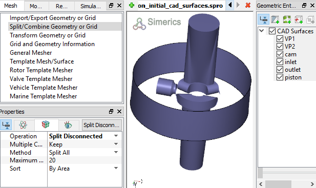
Figure 6.373 - Split of CAD surfaces

Inlet Surfaces
  1. Select CAD Surfaces inlet in the Geometric Entities Panel.
  2. Select Split by Angle from the Operation drop-down list in the Properties Panel.
  3. Enter 50 deg for Angle, click Split by Angle. Three new CAD Surfaces are created in the Geometric Entities Panel.
  4. Rename CAD Surfaces inlet_01, inlet_02 and inlet_03 as inlet_walls, inlet_inlet and inlet_mgi_VP respectively .


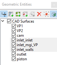
Figure 6.374 - Inlet surfaces


Outlet Surfaces
  1. Select CAD Surfaces outlet in the Geometric Entities Panel.
  2. Select Split by Angle from the Operation drop-down list in the Properties Panel.
  3. Enter 50 deg for Angle, click Split by Angle. Three new CAD Surfaces are created in the Geometric Entities Panel.
  4. Rename CAD Surfaces outlet_01, outlet_02 and outlet_03 as outlet_walls, outlet_outlet and outlet_mgi_VP respectively .


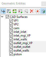
Figure 6.375 - Outlet surfaces


Piston Surfaces
  1. Select CAD Surfaces piston in the Geometric Entities Panel.
  2. Select Split by Angle from the Operation drop-down list in the Properties Panel.
  3. Enter 75 deg for Angle, click Split by Angle. Four new CAD Surfaces are created in the Geometric Entities Panel.
  4. Rename CAD Surfaces piston_01, piston_02, piston_03 and piston_04 as piston_cylinder, piston_cap, piston_wall and piston_mgi_VP respectively.


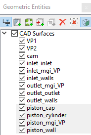
Figure 6.376 - Piston surfaces

Valve Plate Surfaces
  1. Select CAD Surfaces VP1 in the Geometric Entities Panel.
  2. Select Split by Angle from the Operation drop-down list in the Properties Panel.
  3. Enter 75 deg for Angle, click Split by Angle. Six new CAD Surfaces are created in the Geometric Entities Panel.
  4. Rename VP1_02 and VP1_03 as VP1_mgi_piston and VP_mgi_inlet respectively.
  5. Select CAD Surfaces VP2 in the Geometric Entities Panel.
  6. Enter 75 deg for Angle, click Split by Angle. Six new CAD Surfaces created in the Geometric Entities Panel.
  7. Rename VP2_02 and VP2_04 as VP2_mgi_piston and VP_mgi_outlet respectively.
  8. Select CAD Surfaces as shown in Table 6.14. Select Combine from the Operation drop-down list in the Properties Panel.
  9. Click Combine and rename with corresponding names as shown in Table 6.14.


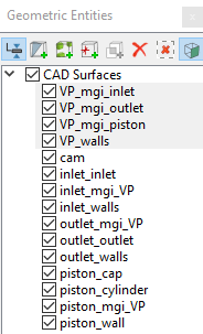
Figure 6.377 - Valve plate surfaces

CAD Surfaces Rename as
VP1_01, VP1_04, VP1_05, VP1_06, VP2_01, VP2_03, VP2_05, VP2_06 VP_walls
VP1_mgi_piston,VP2_mgi_piston VP_mgi_piston

Table 6.14 - Combine CAD surfaces


´ Note: Splitting of the surfaces can also be done by mouse selection using the Split by Mouse option from the Method drop-down list in the Geometry Tab of Properties Panel.


Copyright © 2023 Simerics Inc.,