|
You are here: Fluid Machinery Templates and Tutorials > Radial Piston Pump > Radial Piston Pump Tutorial > Building the Mesh
|
Building the Mesh
This section describes the step-by-step procedure for preparing the mesh for the radial piston pump. The Rotor Template Mesher is used to create the piston-cylinder assembly mesh and the General Mesher is used to create the mesh for the inlet, outlet and the valve plate.
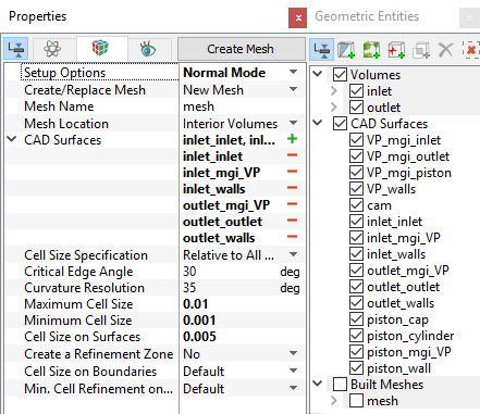
Valve plate Mesh
|
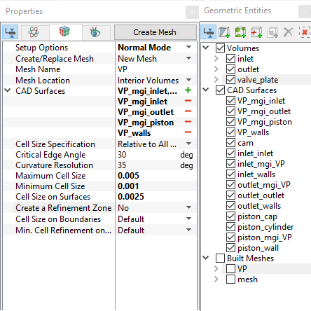
Figure 6.379 - Valve plate mesh settings |
| Boundaries | Rename as |
|---|---|
| VP_walls, VP_walls_1 | VP_walls |
| VP_mgi_piston, VP_mgi_piston_1 | VP_mgi_pistons |
Table 6.15 - Connect and rename boundaries
| ´ | Note: Two connected Volumes, such as the inlet and valve_plate, valve_plate and outlet can not be meshed together using the General Mesher. |
Radial Piston - cylinder assembly Mesh
|
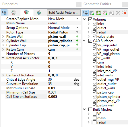
Figure 6.380 - Radial piston - cylinder mesh settings |
|
Note: The imported geometry does not include any leakage gap by default. The parameters for the gaps can be adjusted by selecting a Advanced Mode under Setup Options in the Properties Panel. |
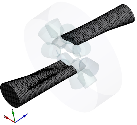
Figure 6.381 - Inlet and Outlet mesh |
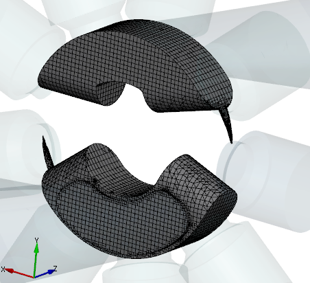
Figure 6.382 - Valve plate mesh |
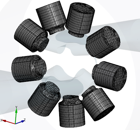
Figure 6.383 - Piston-cylinder assembly mesh |
Create interfaces
In this section, the Mismatched Grid Interfaces (MGIs) are generated between boundaries.
The steps to create the MGIs are shown below:
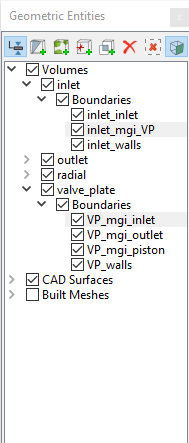
- Geometric Entities Panel > Volumes > Boundaries, select Boundaries as shown in Table 6.16.
-
Click Connect Selected Boundaries via MGI
 icon to create the MGI entities (see, Figure 6.384).
A group display of entities can be viewed using the Group Entities by Volumes/Types ![]() icon at Geometric Entities Panel toolbar.
icon at Geometric Entities Panel toolbar.
| Connecting interfaces | Boundaries | Entity |
|---|---|---|
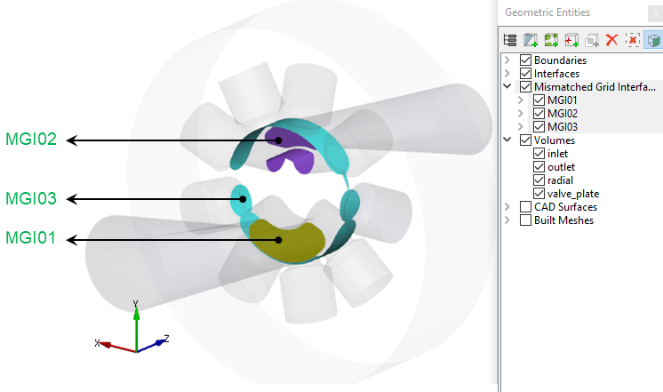
| Inlet and valve plate | inlet_mgi_VP, VP_mgi_inlet | MGI01 |
| Outlet and valve plate | outlet_mgi_VP, VP_mgi_outlet | MGI02 |
| Pistons and valve plate | piston_mgi_VP, VP_mgi_piston | MGI03 |
Table 6.16 - Creating interfaces
The new entities are created under MGI in Volumes (see, Figure 6.385).
|
Note: If MGIs are created by connecting the wrong boundaries, delete the created MGIs by clicking Delete Selected Geometric Entity |