6.12.1 Geometry and Domain
The simulation of the rolling piston compressor requires understanding of the geometry and the fluid domain enclosed by the surfaces of the compressor. The general fluid volume of the rolling piston compressor and prerequisite steps, before taking into Simerics-MP+ are described as follows:
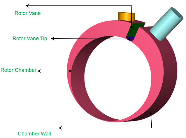
Figure 6.672 - Rolling piston domain
Prerequisite steps
- The fluid volumes for the rolling piston compressor consist of Inlet, Outlet ports, Chamber wall, Vane tip and Vanes.
- Incase of Rolling Piston compressor application, the template requires Chamber wall and Vane tip surfaces for rotor chamber.
- Incase of Cam application, the template requires Rotor surface along with Chamber wall and Vane tip surface for rotor chamber.
- The template creates the leakage gaps based on the values provided. Hence, the fluid volumes should be imported without clearances.
Fluid Domain
The fluid volume in a rolling piston compressor is defined by CAD Surfaces which enclose them. This compressor model primarily consists of the following volumes: Inlet, Outlet, and Rotor chamber as shown in Figure 6.673.
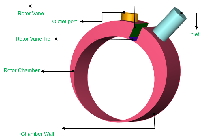
Inlet: The fluid enters the compressor through the inlet boundary. Pressure is generally specified as a boundary condition at the inlet, while the other surfaces of the inlet volume are treated as walls.
Rotor Chamber: This is the rotor chamber, where fluid gets sucked and compressed. The rotor chamber is obtained after meshing using Rotor template mesher.
Outlet Port: The fluid exits the compressor at the outlet boundary. Pressure is generally specified as a boundary condition at the outlet, while the other surfaces of the outlet volume are treated as walls. The outlet port is usually attached with a valve.
For an example of the rolling piston compressor simulation, refer Rolling Piston Tutorial.